Many ports around the world cannot accommodate very large container vessels (VLCVs) due to ship-to-shore crane height and reach restrictions, as well as the draft of container vessels. When accounting for high cost and environmental impacts, it is often prohibitive, if not impossible, to deepen access channels and harbors, and retrofit quays and topside cranes. Additionally, to create greener and more efficient facilities, ports are maximizing train delivery of containers to and from ships because this is the most sustainable and efficient way to move cargo. In some cases, these same ports would use their facilities for floating WTG support, if they could.
Accounting for these factors, a modular floating terminal that can be configured to address a port’s specific needs has been developed. Using a port’s existing infrastructure and facilities, the floating terminal leverages offshore deep water, has a limited environmental impact, is impervious to sea-level rise and can be rapidly implemented.
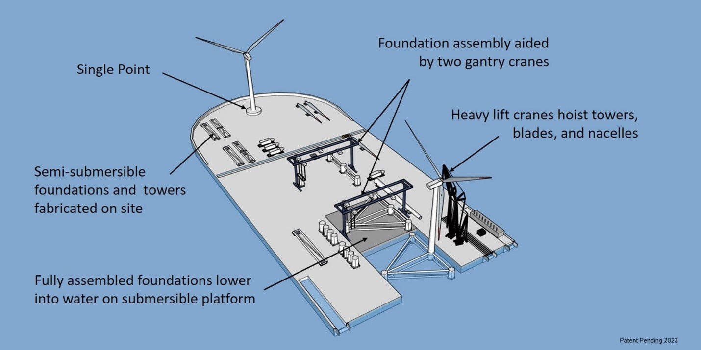
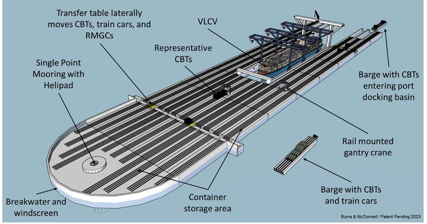
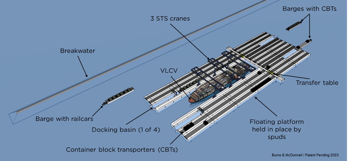
Using a floating terminal to transfer containers to and from VLCVs significantly increases the potential delivery of containers to and from ships by train and reduces container double handling due to bundling and direct-to-rail loading. When the floating terminal is used for offshore wind turbine staging and integration, manufacturing and fabrication, and operations and maintenance, the structure can be configured to support building various floating foundations, including barge, spar buoy and different tension-leg types, and semi-submersibles (Figure 1), as well as the towers supporting the WTGs. Finally, the floating terminal can be repurposed as a container transfer facility upon decommissioning.
Financial and environmental considerations, including shallow channels or expensive retrofitting projects, may limit a port's ability to increase throughput and functionality. A very large floating structure (VLFS) can serve this purpose by supporting the staging and integration, manufacturing and fabrication, and operations and maintenance of floating wind turbine generators (WTGs). Subsequently, the VLFS can be decommissioned and repurposed as a container transfer terminal.
Many ports around the world cannot accommodate very large container vessels (VLCVs) due to ship-to-shore crane height and reach restrictions, as well as the draft of container vessels. When accounting for high cost and environmental impacts, it is often prohibitive, if not impossible, to deepen access channels and harbors, and retrofit quays and topside cranes. Additionally, to create greener and more efficient facilities, ports are maximizing train delivery of containers to and from ships because this is the most sustainable and efficient way to move cargo. In some cases, these same ports would use their facilities for floating WTG support, if they could.
Accounting for these factors, a modular floating terminal that can be configured to address a port’s specific needs has been developed. Using a port’s existing infrastructure and facilities, the floating terminal leverages offshore deep water, has a limited environmental impact, is impervious to sea-level rise and can be rapidly implemented.
Using a floating terminal to transfer containers to and from VLCVs significantly increases the potential delivery of containers to and from ships by train and reduces container double handling due to bundling and direct-to-rail loading. When the floating terminal is used for offshore wind turbine staging and integration, manufacturing and fabrication, and operations and maintenance, the structure can be configured to support building various floating foundations, including barge, spar buoy and different tension-leg types, and semi-submersibles (Figure 1), as well as the towers supporting the WTGs. Finally, the floating terminal can be repurposed as a container transfer facility upon decommissioning.