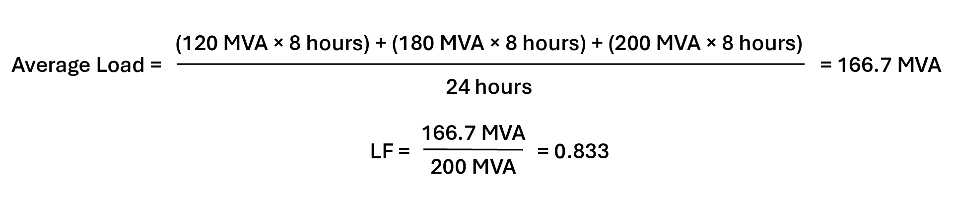
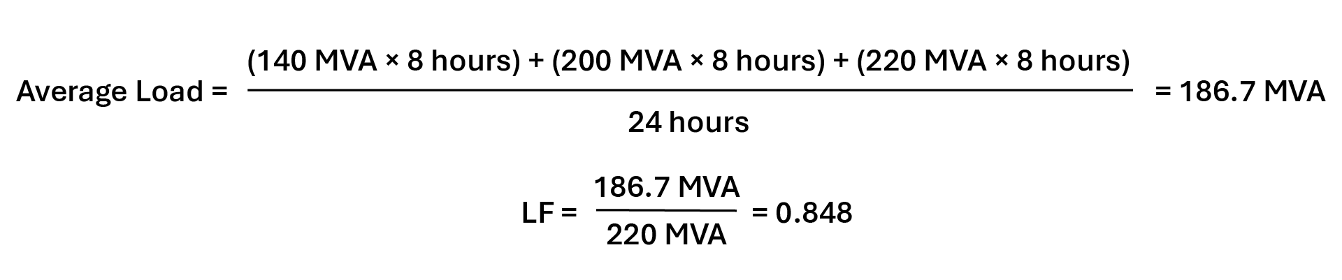
So, the overall load factor of the LILO cable system is approximately 0.85, significantly lower than the 1.0 load factor that would be utilized for a radial tap. This distinction is critical and must be accounted for during planning and cable sizing calculations, as many underground cable systems are thermally limited. Small changes in load factor can significantly impact allowable ampacity and emergency loading capability. Of course, in this example the cable sizes would be vastly different for 20 MVA versus 186.7 MVA, but it does help show the effect that adding a new load can have on the existing load factor.
Transient Preload
Directly correlated to the load factor is the transient preload, typically expressed as a percentage of the total full load ampacity. It is defined as the load on the cable system immediately prior to a short- or long-term emergency condition. In the case of a 1.0 load factor already having been determined to be applicable, the preload must be set at 100% to match. This is highly important for radial tap configurations, due to the radial taps typically operating at a 1.0 load factor. For LILO configurations, a lower preload may be acceptable, depending on the existing line’s load factor and expected total load change with the data center load added. Care should be taken to determine an acceptable preload, as incorrect assumptions can lead to overestimation of emergency ratings, which is particularly critical for radial configurations where no alternate supply path exists. The most conservative option is to assume a 100% preload.
Continuous Loading
The continuously loaded nature of a data center can introduce other challenges, especially in a radial tap configuration when the cables are nearly always at 100% of their maximum load. In an underground cable system, heat generated by the cables dissipates into the surrounding concrete, backfill, soil and, eventually, the air. Each material has a unique thermal resistivity dry-out curve, which shows the relationship between the moisture content of the material and its thermal resistivity. A higher thermal resistivity indicates the material is worse at transferring heat away from the cables, thus reducing the cable ampacity. As the moisture content decreases in a material, the thermal resistivity typically increases.
With the cable steadily at 100% load, there is no time for the soil to recover and cool down. This can lead to soil dry-out, increasing the thermal resistance and making heat dissipation even more difficult. Engineered backfills with specific thermal resistivities can help mitigate this. Geotechnical surveys should be conducted during planning and design to determine if the existing soil is viable or if an engineered backfill is required. Similarly, the cables being at 100% load means the mutual heating between the cables is never given a chance to decrease, causing long-term steady-state ampacity to be lower than it otherwise could be.
The ampacity challenges introduced by continuous loading are most significant in radial tap configurations. They can be mitigated by properly sizing the cables to account for loading conditions so there is a larger margin between the cable’s maximum rated temperature and its actual temperature. If there are plans to use the radial tap as a steppingstone to a LILO configuration, it might be possible to use a larger-than-needed cable for the radial tap connection so the same cables can later be used in the LILO connection. While the overall capacity of the cables will need to be much greater in the LILO configuration to account for the new loads being added to the existing data center load, the continuous loading challenges will be mitigated when transferring from the tap to the LILO.
Of course, if the cable size is already at or near the maximum size (around 6,000 kcmil), cable upsizing is no longer an option. Alternative solutions include increasing the number of parallel cables per phase or increasing the voltage class. If the plan is to transfer the cable system from a radial tap to a LILO and use the same cables, ampacity calculations should be performed on both the radial tap installation and the LILO, adjusting the parameters and required ratings as needed.
Contingency Scenarios
Another important consideration for radial tap configurations is performance under an N-1 contingency scenario. In this context, N-1 refers to the loss of one supply circuit while maintaining service to the data center. To support this, multiple independent radial circuits might be installed, each capable of supplying the load.
If one circuit is taken out of service, the remaining circuit or circuits could be required to carry a portion or the entirety of the data center load. This condition can be highly thermally limiting, particularly given the continuous high-load nature of data centers. As a result, N-1 operation must be carefully considered during ampacity modeling, including appropriate assumptions for load sharing, transient preload and emergency ratings. This approach requires multiple independent source circuits to be available for interconnection, which may not always be feasible, depending on the existing transmission system.
Designing the cable system with an N-1 contingency case in mind can improve reliability for radial configurations, but it might still provide less operational flexibility than a LILO configuration, in which alternate supply paths are inherently available.