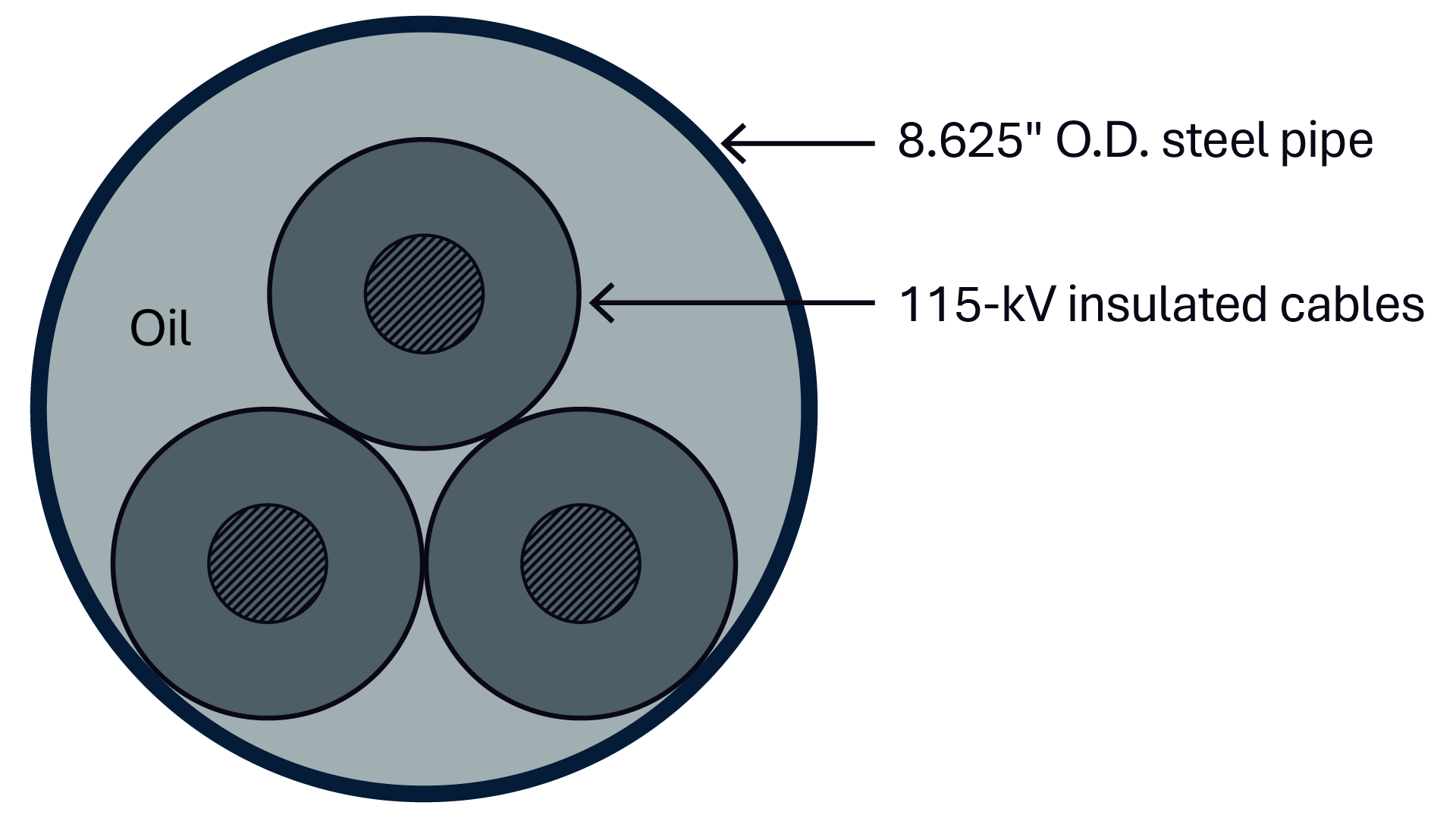
Figure 1: HPFF cable cross-section.
Figure 1: HPFF cable cross-section.
Utilities in the U.S. currently operate nearly 4,000 miles of HPFF transmission cables, with the bulk of them over 50 years old. The challenge for utilities is determining when an old cable should be replaced and how much of the existing system should remain part of the next generation of assets.
For some systems, targeted rehabilitation may provide the appropriate bridge to a future replacement program. Others may justify reconductoring and comprehensive pipe rehabilitation. Where continued operation of a fluid-filled system is undesirable, installing a new solid-dielectric cable system within portions of the existing civil infrastructure might provide another path. Where existing conditions, capacity needs or long-term system requirements make reuse impractical, full replacement ultimately might be the more appropriate investment.
Each choice comes with a very different lifespan, as well as differing reliability, environmental exposure, outage requirements, constructability and capital cost.
Utilities already know these HPFF systems are aging. The consequential question is whether they are renewing them strategically or extending them through incremental repairs.
One reason HPFF renewal is difficult is that these systems rarely reach the end of their useful life as a single asset. The cable may still be electrically serviceable while corrosion progresses on the surrounding steel pipeline. A pipeline may remain structurally viable while its cathodic protection system no longer performs as intended. A splice, termination or manhole penetration may become a recurring repair issue even though the rest of the circuit remains in good condition.
Environmental and operational exposure are also changing:
Such challenges are compounded by a diminishing pool of manufacturers, specialty contractors and experienced personnel able to supply, install, test and maintain HPFF-specific equipment and accessories. This combination increases the time required to field the materials and resources for reactively managing unanticipated failures and fluid releases from the aging infrastructure.
HPFF renewal should be approached as a system-renewal project, with the cable, steel pipe, corrosion-protection system, dielectric-fluid system and associated civil infrastructure evaluated together.
Before detailed design begins, utilities should determine which renewal philosophy aligns with the condition and long-term purpose of the asset on their electrical system, as well as the investment objective and limitations. Four basic approaches cover much of the decision space.
Target selected weak points while retaining the existing cable and pipe system. This can include splice or termination replacement, localized cathodic-protection repairs or component replacement, pumping-system repairs, or dielectric fluid maintenance or replacement.
Retain the existing steel pipeline while replacing the existing cables with new HPFF cables along with associated electrical components. Identify and mitigate localized pipe or coating defects, and upgrade corrosion-protection and manhole components as needed.
Transition from a fully fluid-filled cable system to solid-dielectric cable while reusing viable portions of the existing civil infrastructure. This may include installing solid-dielectric cable within the existing steel pipe or connecting to a retained HPFF section through a specialized transition joint.
Abandon or remove the existing HPFF system and construct new civil infrastructure for a modern solid-dielectric cable system.
A sound renewal program begins before a specific replacement approach or cable design has been selected. The first step is to understand the condition, configuration and known limitations of the existing assets. Historical drawings may be decades old. Pipeline elevations, bends or underground conflicts may have changed or may never have been documented accurately. DGA results could be declining. Cathodic-protection records may reveal persistent underprotection or interference, while maintenance history may identify recurring leaks, splice issues or manhole deterioration.
Next, define the investment objective and limitations. Is the goal a short-term reliability intervention, several decades of additional service life, increased transmission capacity, elimination of environmental risks due to dielectric fluid, or a combination of these outcomes? A near-term reliability investment and a 30- to 40-year asset-renewal program should not produce the same scope.
Once the asset condition and investment objectives are understood, evaluate the feasibility of the available renewal options. This evaluation should include technical compatibility, constructability, outage requirements, capacity, permitting, long-term reliability and cost.
When reconductoring with HPFF cable emerges as the preferred renewal path, feasibility analysis can identify details that initially appear minor. One of the most important lessons in reconductoring is that an existing pipeline that successfully accommodated the original cable does not automatically accommodate a modern HPFF replacement cable.
Jam ratio and fill ratio are obvious examples. In one HPFF rehabilitation program, relatively small changes in cable insulation thickness moved the calculated jam ratio from an acceptable value into the range associated with jamming potential during installation. In that instance, the same initiative identified a 67% fill ratio in certain 6-inch pipes, above the stated industry best practice target used for that evaluation, with the primary concern being reduced fluid flow and circulation capability.
Fill ratio is therefore more than a geometric check. Increasing conductor size can improve electrical capacity, but it also occupies volume previously available to dielectric fluid. That can change fluid circulation and hydraulic behavior and could impact heat transfer, particularly where forced circulation or future forced cooling is part of the operating strategy. Because the fluid is also integral to the HPFF insulation system, the complete thermal, hydraulic and dielectric performance of a high-fill-ratio design should be evaluated rather than treating an acceptable jam ratio as the only criterion.
Older HPFF cables may have been installed with brass or zinc-alloy skid wires, while current Association of Edison Illuminating Companies (AEIC) requirements generally call for nonmagnetic stainless steel skid wires under AEIC CS2-23. Where a replacement cable uses stainless steel skid wires in a system originally designed around brass or zinc-alloy construction, the potential impact on existing stainless steel riser pipes and other steel pipe sections should be evaluated.
Differences in skid-wire material can change the cable-to-pipe interface friction during pulling and may affect pulling forces and localized pipe wear. Replacement cable construction and pulling assumptions should therefore be reviewed with the cable manufacturer, with particular attention to riser pipes and other locations where contact forces may be concentrated.
If the steel pipeline is expected to remain in service for decades, corrosion protection should be treated as a core part of the renewal program. Modernization might include impressed current cathodic protection (ICCP), using dedicated anode beds and rectifiers to provide controlled protective current to the pipe. The system should be developed by experienced corrosion specialists who understand ICCP design and the interactions that can occur in pipe-type cable systems, including nearby grounding grids, parallel metallic facilities, steel casings, circulation fluid return lines and stray-current sources.
The long-term performance of the cathodic-protection system depends as much on long-term monitoring and maintenance as on the initial design and installation. Remote monitoring, easily accessible test stations, documented operating criteria, and a robust inspection and maintenance program are needed to confirm that the system remains properly operating and effective throughout its service life. A well-designed system that is not routinely monitored and maintained can lose effectiveness over time, resulting in line outages, increased down time, and increased repair time and expense.
Manhole penetrations deserve similar attention. These transition locations can combine coating damage, moisture exposure and difficult access. Replacing degraded pipe sections, penetration sleeves and aging seals while the pipeline is already empty may prevent a localized weakness from becoming the unreliable weak link in an otherwise renewed system.
Fluid replacement appears simple until two circuits share common pumping equipment. A utility may not be able to completely drain a shared pump house fluid storage tank while the companion circuit remains energized. Staged replacement can therefore create a temporary — and to some extent continuing — mixture of old and new dielectric fluid. That matters because future DGA results must be interpreted against the condition of the mixed dielectric fluid. Baseline samples established both after reconductoring and again after the system has had time to stabilize provide a critical reference for future investigations.
Alternatives can introduce their own risks. A portable pump house and temporary fluid tank could theoretically allow complete turnover of the existing fluid in a dielectric fluid storage tank, but doing so may remove the portable unit from availability for emergency service elsewhere, create a single point of failure, require additional temporary monitoring and increase operating complexity. The right fluid-management approach therefore cannot be separated from outage planning and system operations.
The technical condition of the pipe may support reconductoring while the physical environment around it argues for another strategy. Urban underground transmission routes frequently occupy corridors already crowded with utilities, structures and transportation infrastructure. Excavating every defect could require extensive traffic-control plans and multiple permits. Full replacement with a solid-dielectric cable system can magnify those impacts because a new duct-bank system typically needs more excavation width and additional manhole space than existing pipe-type installations.
Conversely, that same congestion is often the strongest argument for reuse. If a structurally viable steel pipeline already provides a continuous path through a highly constrained corridor, preserving that civil asset can avoid extensive utility coordination and street disruption.
A program of multiple upgrades can use more than one solution: targeted repairs for one circuit, reconductoring and pipe rehabilitation for another, hybrid retrofit for a third, and full replacement where condition or long-term requirements justify it.
The most important principle in managing aging HPFF systems is the shift toward making renewal decisions before a leak, failure or emergency outage dictates the next step. Repeated reactive repairs might keep a system operating in the near term, but they also defer larger decisions until fewer options remain. Outage availability may be constrained, pipe conditions may be uncertain, replacement-cable compatibility may be unverified, and permitting and procurement may be compressed by schedule.
A structured HPFF renewal road map changes that sequence. Utilities can identify systems approaching critical condition, gather the information needed to understand the complete asset, define the desired service-life extension, compare renewal pathways, and evaluate key constraints — including pipe condition, cable geometry, skid-wire construction, pulling feasibility, fluid circulation, cathodic protection, manhole condition, outage strategy and urban constructability — before committing to a solution.
HPFF systems do not become obsolete simply because they are old. In many cases, the steel infrastructure beneath the street still has significant remaining lifespan and value. The greater risk is allowing recurring component repairs to postpone a deliberate system-level decision until deterioration or failure determines the path forward.