White Paper

Power Substation Safety With Arc-Flash Studies

Conducting arc-flash studies in electrical substations is essential for worker safety in both low- and high-voltage working environments. Choosing the right approach helps predict and mitigate incident energy risk.


Working in a substation is dangerous. In addition to short circuit currents and fault clearing time, elevated work spaces and using tools may increase the danger level. With so many possibilities for the elevation of incident energy, it's recommended that substation operators be aware of all worst-case scenarios for potential arc-flash hazards. An arc-flash study can help raise such awareness and, in turn, help operators reduce possibilities for exposure to such hazards.

An electrical explosion creates an arc flash (light and heat from the explosion) and arc blast (secondary pressure wave). This sudden explosive electrical arc results from a short circuit incident through the air. In normal conditions, air works as an insulator, which is not conductive. During any arc-flash incident, however, air can become ionized and conductive.

The air surrounding an arc flash can heat to between 5,000 and 35,000 degrees Fahrenheit in a fraction of a second. The resulting conductive plasma, high sound levels and extreme temperatures can cause skin burns, respiratory issues, hearing loss, eye damage and death.

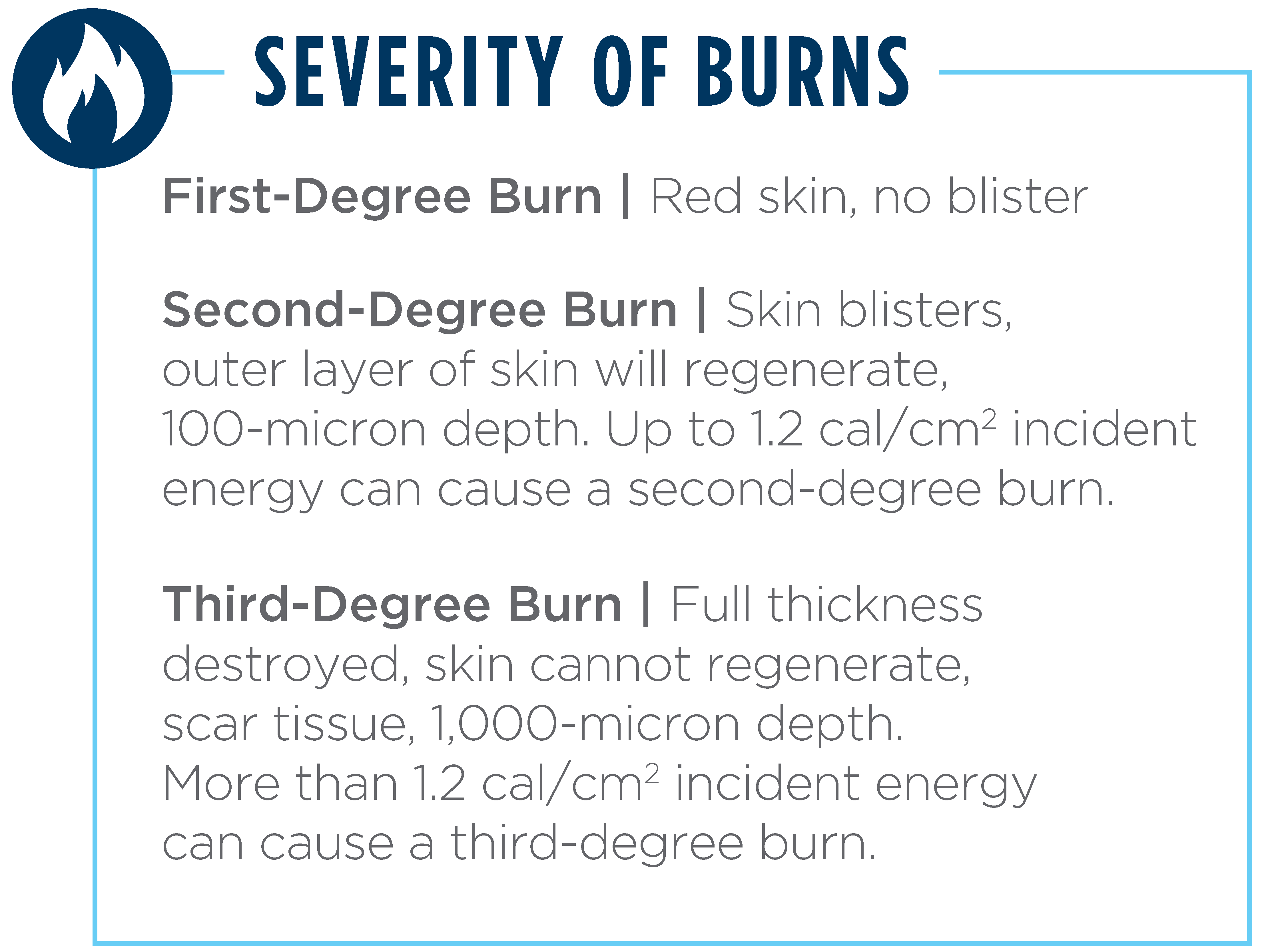
The basic unit of arc-flash hazard levels is incident energy, which is measured in calories per square centimeter. Incident energy is generated during an electric arc event and is the amount of thermal energy impressed on a surface at a certain distance from the source. The incident energy level of 1.2 cal/cm2 on bare skin for less than one second is deemed safe incident energy.


Read The White Paper

Working in a substation is dangerous. In addition to short circuit currents and fault clearing time, elevated work spaces and using tools may increase the danger level. With so many possibilities for the elevation of incident energy, it's recommended that substation operators be aware of all worst-case scenarios for potential arc-flash hazards. An arc-flash study can help raise such awareness and, in turn, help operators reduce possibilities for exposure to such hazards.

An electrical explosion creates an arc flash (light and heat from the explosion) and arc blast (secondary pressure wave). This sudden explosive electrical arc results from a short circuit incident through the air. In normal conditions, air works as an insulator, which is not conductive. During any arc-flash incident, however, air can become ionized and conductive.

The air surrounding an arc flash can heat to between 5,000 and 35,000 degrees Fahrenheit in a fraction of a second. The resulting conductive plasma, high sound levels and extreme temperatures can cause skin burns, respiratory issues, hearing loss, eye damage and death.

The basic unit of arc-flash hazard levels is incident energy, which is measured in calories per square centimeter. Incident energy is generated during an electric arc event and is the amount of thermal energy impressed on a surface at a certain distance from the source. The incident energy level of 1.2 cal/cm2 on bare skin for less than one second is deemed safe incident energy.

Prevent Arc-Flash Hazards

One can avoid arc-flash incidents by not working with electrically live equipment and parts, but this is not always possible. By integrating four strategies into an arc-flash safety program, organizations can reduce the likelihood of arc-flash incidents, mitigate their impact when they occur and create a safe working environment for employees.

  • Predict: Eliminate an arc-flash hazard by considering the operating environment potential scenarios and designing the risk out of a work area.
  • Prevent: Substitute tools, equipment or instructions and use safer alternatives to complete tasks. Isolate and guard work actions through revised engineering controls.
  • Publish: Implement training and improve work practice guidelines using administrative control to protect working environments.
  • Protect: Use the correct personal protective equipment (PPE), which can offer a last resort of protection when working on electrically live equipment.

Identify the Incident Energy

An arc-flash study determines the state of an electrical transmission and distribution system to identify the incident energy, or heat from an arc flash, to a worker at any point while working with the system. Equipment can be labeled by determining the specific incident energy level and appropriate precautions taken. Without this analysis, workers cannot identify how hazardous electrical equipment or systems might be.

Arc-flash hazard assessments are required every five years, as per National Fire Protection Association (NFPA)-70E Article 130.5. Arc-flash system analysis must also be performed after any electrical equipment replacements or upgrades that may affect incident energy levels.

The NFPA-70E standard outlines safe electrical work practices. The Institute of Electrical and Electronics Engineers (IEEE) 1584 standard provides the arc-flash calculations to determine arc-flash boundary and incident energy.

Operators must be familiar with the standards, regulations and laws around arc-flash hazards to understand the risks, protect and train workers, and mitigate arc-flash hazards. Conducting an analysis helps identify the possibility of arc-flash hazards and changes that need to be made to further protect workers from serious injuries or death, as well as prevent property loss or penalties. System analysis, as part of an electrical hazard assessment to identify arc-flash hazards, must occur on a regular basis or whenever needed.

In addition to meeting regulations, a study of arc-flash risk can be wide in scope and provide substations with valuable operating information. Electrical system fault current evaluation, PPE recommendations, correct equipment labeling, incident energy mitigation processes, and safety guidelines and training programs are all potential deliverables.

To get the most out of arc-flash analysis, it is essential to assess different voltage environments.

Arc-Flash Study: Low Voltage

When it comes to arc-flash incidents, the most common occur in low-voltage situations. In most cases, an arc-flash incident starts from a single fault, either line-to-ground or line-to-line. But with the ionization of air during an arc-flash event, a worst-case scenario can emerge: the single-phase fault can turn into a three-phase fault, all within a fraction of a second. That’s why it’s important to conduct a three-phase arc flash in an arc-flash study, as supported in the IEEE-1584 standard for electrical installations ranging from 208 V to 15-kV.

In some cases, a single-phase arc-flash incident could be the worst-case scenario, depending on the fault current and clearing time. A single-phase arc-flash study can be performed using single-phase fault current estimation from a three-phase fault current.

Most substations require a separate station service power supply system and, due to requirements for uninterruptable power supply, workers must work on the low-voltage energized parts. Substation power supply systems may consist of one or multiple station service transformers from different power sources, standby generators, throw-over switches, protective devices and power supply panels.

For substation arc-flash studies, the engineer must consider all different scenarios of power supply to identify the worst-case incident energy levels. It is recommended that the arc-flash study be started during the design phase of a new substation. Sometimes, it may be hard to coordinate the protective devices and acceptable incident energy levels at the same time without changing the miniature circuit breakers (MCBs). Using solid-state type main MCBs with variable overcurrent settings allows the engineer to consider various adjustments to trip time and bring the incident energy to an acceptable range.

For existing substations, protective device coordination may need to be sacrificed to achieve acceptable incident energy without replacing any protective device or taking measures for other mitigation alternatives.

It is common practice for utility companies to use a single category of PPE (8 cal/cm2 PPE is commonly used) for most of the work inside the substations. It is the responsibility of the study engineer to find a way to reduce the incident energy below 8 cal/cm2. However, reduction to below 8 cal/cm2 is only sometimes possible with a significant change in the power supply system. In that case, a higher category of PPE, such as up to 40 cal/cm2, is required for workers. Incident energy levels above 40 cal/cm2 means working on the energized parts is prohibited.

A low-voltage arc-flash study can be performed using any power system software that supports the IEEE-1584 standard.

Arc-Flash Study: High Voltage

IEEE-1584 does not support a high-voltage arc-flash study. IEEE has not yet performed enough research, modeling, testing and analysis to develop a study for high-voltage arc-flash incidents.

As a guide, substation clearances for high-voltage equipment typically cover the safe movement of workers without tools inside the substation. However, using tools may lower the clearance and create an arc-flash hazard. Medium voltage live works have been increased recently for operation and maintenance. Switching operation, fuse disconnect of a station service voltage transformer (SSVT), and insulator or pole change now require assessing the arc-flash level at different medium-voltage substations or lines.

Because medium- and high-voltage arc-flash studies are not yet required, a standardized method for evaluation and assessment has not been defined. Several analytical options are available.

While both IEEE-1584 and NFPA-70E Annex D discuss the Ralph Lee method, neither standard recommends using this method to calculate arc-flash incident energy. NFPA-70E states that the Lee method is very conservative in calculating incident energy for electrical installation over 600 V and becomes more conservative as the voltage increases.

Based on a paper published by IEEE in 1987, the Lee method can be applied to a three-phase system in open-air substations over 15-kV with a gap between conductors of more than 10 inches. This method is based on the theoretical behavior of the arcs. The Lee method has not been verified by measurement or tests. Also, the arc voltage is extremely large at medium voltages and gives high incident energy.

OSHA 1910.269 provides examples of the specific method that can be used to calculate high-voltage arc-flash incident energy reasonably using the Lee method and ArcPro software developed for high-voltage incident energy. The software, however, is not stand-alone power system software and needs short-circuit currents at the location of the arc-flash incident.

The Terzija/Koglin method was developed from a paper, “Long Arc in Free Air: Laboratory Testing, Modelling, Simulation and Model-Parameters Estimation.” A supporting study derives the main features of a long arc initiated under laboratory conditions at the FGH-Mannheim high-power test laboratory in Germany. The experiment aimed to model long arcs in free air in the simplest possible way, while still retaining the arcs’ dominant features.

The Electric Power Research Institute (EPRI) performed comprehensive tests and experiments for a high-voltage arc-flash study and, as a result of these experiments, developed empirical equations. The formula developed provides a method to calculate incident energy and can be effectively used to determine the heat flux and incident energy for open-air, line-to-ground arc faults in overhead power distribution and transmission systems. Incident energy calculations for open-air conditions were mainly designed for line-to-ground faults between 1- and 800-kV and commercial software extended the results to line-to-line and three-phase faults.

While commercial power system software uses all these methods, there is no direct answer to which method is good or better. However, study engineers can find the worst-case result by using sensitivity analysis. Sensitivity analysis can be performed to see how the incident energy varies for different methods with various other parameters such as varying voltage regulation plus or minus 10%, arc-gap distance, approach distance, fault current and fault clearing time. Also, for a high-voltage arc-flash study, study engineers should better understand medium- or high-voltage protective schemes, relay settings and coordination at the local and remote end of any substation.

DC Arc-Flash Study

As per NFPA-70E, any voltage greater than 100 Vdc and 40mA DC can be considered a source of hazardous energy. Direct-current electrical hazards include thermal, shock, arc-flash and acoustic hazards.

The IEEE-1584 standard does not cover a DC arc-flash study; the only guide for this flash study is NFPA 70E Annex D.5.

Using the few published papers that exist on DC arc-flash analysis, commercial software companies have integrated the DC arc-flash methods into their software, but, unfortunately, not many tests have been done. A recent study shows that arcing cannot sustain long enough, which could create an arc-flash risk for workers in a small DC battery system in a substation of voltage 125-150 Vdc. However, this is not true in photovoltaic (PV) or battery energy storage systems (BESS). Therefore, evaluating the DC arc-flash hazard level at all DC facilities is essential.

NFPA-70E Annex D.5 discusses the maximum power method for a DC arc-flash study. Maximum power transfer occurs when the source impedance equals the load impedance. Therefore, the maximum power method concept is that the arcing voltage is 0.5 of the system voltage in a DC arc-flash incident. In this calculation, it has been assumed that the arcing fault current equals 0.5 of the bolted fault current. This method is very conservative, and the range of overestimation is between six and 10 times. This method will give high-incident energy for higher voltage and can be applied up to 1,000 V dc.

The Stokes/Oppenlander method is a double iterative ideal for PV systems. Based on laboratory tests, the empirical method was derived from the test of free-burning vertical and horizontal arcs between electrodes in open air. The only way to solve the equations of this method is iterative because of their nonlinear nature. The voltage across the arc for the Stokes/Oppenlander method is a function of the gap between the conductors.

The Paukert method is based on the examination of arcing fault data from several researchers that was compared to Paukert’s work for both vertical and horizontal arcs. The result was a set of equations for different electrode gaps and arcing current ranges.

The Stokes/Oppenlander or the Paukert methods can be used for DC arc-flash study. However, there could be some variations in results between these two methods, which can be analyzed by sensitivity study.

Safer Substations

To prevent arc-flash safety incidents, be proactive rather than reactive. Recognizing hazards, identifying potential operating risks and training employees are effective in maintaining a safe workplace.

Comprehensive substation arc-flash studies result in the right power supply system design, correct schemes for medium- or high-voltage equipment and buses, appropriate protective devices and protective gear, and the most cost-effective mitigation alternatives. Reducing the incident energy in substation environments to the acceptable range, along with increased worker training and safety, can be achieved.

The Power of Power

Simple heat generation in a conductor from electric current, H = Power*t = V*I*t = I2*R*t watt-hours ⟶ calories, where V is the system voltage, I represents the short-circuit currents, and t is the time to clear the faults. Also, energy developed during an arc-flash incident is Earc = (K*Isc*V*t)/D2 cal/cm2, where D is the distance from the arc, t is the arc duration and K is a constant.

Energy developed during arc flash is proportionate to short-circuit current, voltage and time. It is also inversely proportional to the square of the distance from the occurrence of the arc flash. Decreasing the operating time of the protective device is the easiest way to reduce the incident energy levels.


Author

Mahfooz Hilaly

Associate Electrical Engineer