White Paper

Pipe Stress Analysis for Pipeline Operators

Proper pipe stress analysis can help improve system integrity, preventing issues such as leaks, equipment failure, foundation stress cracking or anchor bolt failure. This preventive measure can extend equipment life and reduce costs for system operations and maintenance. Effective usage depends on careful modeling of load cases for specific scenarios.


Most common industry design codes, such as ASME B31.3, B31.4 and B31.8, require completing a pipe stress analysis (PSA) on any newly designed facility. The purpose of the analysis is to confirm that under all operating conditions and load scenarios the piping will continue to operate safely and not exceed the pipe material’s allowable stress limits. These piping models are also relied upon in determining the maximum loads on foundations and to check that nozzles’ loads on equipment do not exceed their maximum limits.

Industry design codes only provide general guidance on the allowable stresses and calculation methods to determine commonly encountered stresses. In reality, there are many more factors to consider, some of which are difficult to model. There are best practices and guidelines available to help engineers with stress analysis, but the modeling is not entirely a science. Pipe stress analysis is still an art form, to some extent.


Read The White Paper

Most common industry design codes, such as ASME B31.3, B31.4 and B31.8, require completing a pipe stress analysis (PSA) on any newly designed facility. The purpose of the analysis is to confirm that under all operating conditions and load scenarios the piping will continue to operate safely and not exceed the pipe material’s allowable stress limits. These piping models are also relied upon in determining the maximum loads on foundations and to check that nozzles’ loads on equipment do not exceed their maximum limits.

Industry design codes only provide general guidance on the allowable stresses and calculation methods to determine commonly encountered stresses. In reality, there are many more factors to consider, some of which are difficult to model. There are best practices and guidelines available to help engineers with stress analysis, but the modeling is not entirely a science. Pipe stress analysis is still an art form, to some extent.

Piping engineers typically use software, such as Bentley AutoPIPE CONNECT or Caesar II, to help with this analysis. Such software’s effectiveness, however, is limited by lack of awareness of the full capabilities of these programs and failure to consider some stresses. Ultimately, the piping designer must interpret the results and use them as guidance to refine the station design, lowering the pipe stress while also keeping in mind the constructability, operations and maintenance of the facility.

Challenges

Pipeline operators have some unique concerns that can be addressed with a pipe stress analysis. These include high blowdown reaction forces from transmission lines, the interaction of thermal expansion and soil friction on long pipelines, buried branch connections, the potential for soil settlement, and the effects of using trenchless crossing techniques or pipe casings.

There are many factors to consider when performing a PSA, and a lot of information needs to be gathered by the stress engineer to complete one properly. There is potential for numerous errors or warnings to be generated by the chosen software during the analysis. Some of these may be tolerated, whereas others should be cause for concern. A final quality review is important to verify that all the necessary information was incorporated and the results were interpreted correctly, as even experienced stress engineers can forget something.

Even a thorough PSA cannot eliminate all potential operational issues. In some special cases a vibration analysis, finite element analysis, wake frequency stress calculations, computational fluid dynamics analysis or transient surge analysis might also be necessary.

Modeling

It is critical to start any analysis with a model that closely reflects the final design or as-built piping system. This is typically done by importing the model from CAD software directly into the pipe stress software (see Figure 1). On brownfield projects, engineers must also determine how to account for the impacts of existing infrastructure on new piping.

During conversion it is common to encounter a few errors and things that need to be cleaned up.

Consider adding node points before running an analysis, as there will be no results for segments without nodes. Check that the model is accurate to the current design and all components are assigned the appropriate material properties. Some standard tap assemblies may be omitted to save time if they have been analyzed previously. Break up segments as appropriate and apply soil properties; ground level is a typical location to split line segments. Use the “show model properties” function to confirm that properties and loads have been applied to the appropriate line segments.

Figure 1: M&R station model.

CLICK TO ENLARGE

Boundary Conditions

Every model requires specific boundary conditions to be set to limit the scope of the analysis. PSA models can get very large and result in taking hours to run an analysis, so for large facilities it is recommended to break up each model into sections. Where to divide the facility into different models and how to handle the transition zone between sections are further considerations.

Another unique type of boundary condition involves long pipelines entering or exiting a station. In these cases a virtual anchor length calculation should be performed to determine the length of the pipeline alignment that should be included in the analysis, as it could impact the pipe stresses inside the station.

Engineers should avoid using rigid anchors in most situations, especially at equipment connections, as these can result in dramatically higher pipe stress. They are also unrealistic, as there is nothing that is truly infinitely stiff. Determining these points’ stiffness can be a significant challenge. In general, the stiffer the anchor, the higher that pipe stresses will be at the anchor point and therefore the more conservative the analysis. Stress within the pipe will be higher than actual, but the load on supports outside the equipment will show up lower in the analysis than actual.

Some anchor points may also call for the addition of a thermal anchor movement, such as connections to a tall contact tower. The connection point to the vessel can shift slightly with the vessel as it thermally expands and contracts.

Soil Properties

Many sites have some buried line segments and therefore require soil properties to be applied to evaluate the overburden loads and the resistance to pipe displacement from the soil springs. PSA software will provide multiple calculation methods, such as those from the American Lifeline Alliance or Pipeline Research Council International, and a few standard soil properties to choose from. Ideally, soil properties should be based on geotechnical surveys taken at the site to accurately reflect the conditions, but this information is not always available. Loose sand can be a conservative assumption, as such less-cohesive soils don’t provide as much support to the pipe, resulting in higher structural support loads. However, this isn’t always a more conservative assumption, as more cohesive soils can restrict pipe movement and lead to higher bending moments near branch connections. Engineers should also remember to verify pipe size, depth and trench-laying techniques when applying soil properties.
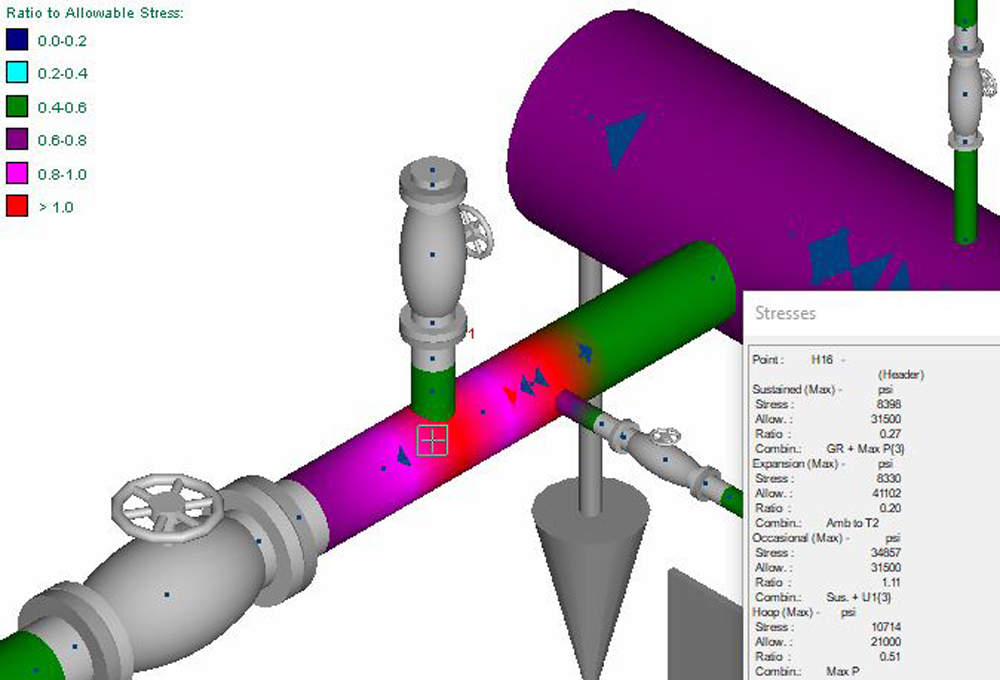
Branch Connections

Piping branch connections are common locations where combined stress might exceed allowable limits. This is due to the stress intensification factors (SIFs) in these locations. Designers should verify that the branch type matches the fitting to be used in the design. Keep in mind that these SIFs are approximations based on code calculations, such as ASME B31.8 Appendix E for common fittings. These SIFs do not account for the number of loading cycles, nor the considerably heavier wall thickness that some cast fittings provide, which can introduce errors into these estimates. One method to improve on the standard branch connections in the PSA model is to use an initial rigid internal segment; a second, thicker-wall short segment to resemble the branch fitting; and then the branch pipe. A user SIF must then be applied manually to the branch segment. In some critical cases, it may be necessary to do a more thorough analysis using a finite element analysis on a 3D model of the part.

Supports

All pipe supports should be included and modeled as closely as possible. There may be more than one acceptable type of support, and a structural engineer should verify that the selection accurately reflects the support design. Translational stiffness, friction coefficients and guide gaps are key factors to determine, and they vary significantly by direction or support type. Designing pipe supports is often an iterative process in which the piping designer approximates an initial, conservative support layout design, then shares the support reactions with a structural engineer to refine the design. Then the analysis is updated to reflect the improved design.

Operational Load Cases

Determining the appropriate pressures and temperature cases to analyze is critical to any PSA. A typical approach is to analyze a common operational scenario or base case and two more extreme operational scenarios, with both at the system maximum allowable operating pressure: one at minimum temperature and the second at maximum operating temperature. Selecting the appropriate temperature range can be challenging, however, because simply using the full design basis temperature range for specified equipment can lead to overstressing and be unrealistic compared to most steady-state transmission line operations. Buried pipelines are typically isothermal in nature and operate at moderate temperatures. There is the added complication of the neutral stress state or ambient temperature that is chosen because in reality this will depend on the weather at the time when the lines are installed. One approach to achieve more realistic results is to separate above-ground and underground line segments and apply different temperature ranges to each.

There may be other unusual operating conditions. For instance, if the discharge cooler at a compressor station fails, the piping downstream can experience much higher temperatures than normal. Another example would be a steam-out on a process line in a refinery.

Seismic Loads

For occasional static earthquake loads, use recent industry code calculations, such as ASCE 2016. The version referenced should match the one used by the local municipality. Apply the appropriate site class, importance and component response factors. The Ss value — the spectral acceleration parameter at short periods corresponding to the mapped maximum considered earthquake — must be determined based on the location. Once the seismic accelerations are determined, it is important to apply these seismic loads in various directions along the X-, Y- and Z-axes.

Wind Loads

For occasional wind loads, engineers can use wind profiles generated using standard ASCE 7-16 or input their own wind pressure profile, using the version of ASCE 7 adopted by the local municipality. For ASCE 7-16 wind load calculations, users should adjust the exposure category, basic wind speed, gust and elevation factors. These can vary based on site conditions, but in most cases it is important to apply wind loads in multiple horizontal axial directions. A 45-degree direction between the primary coordinate axes may also be considered. Wind loads should only be applied to above-ground line segments, not to buried line segments or segments that are inside buildings. The ground elevation must also be correctly defined. Select the lowest grade elevation for a site with a slope.

Snow Loads

Snow loads are not often significant for piping assemblies, and for some sites in warmer locations they are not necessary to consider at all. However, they will need consideration for most Midwest and northern pipeline facilities. ASCE 7-16 ground snow loads are readily available, converted to psi units and applied on a per-unit-area basis in the model.

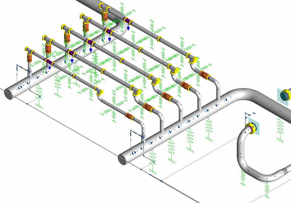
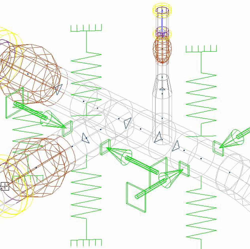
Additional Forces and Displacements

Other loads can be critical design considerations for facilities. These may include blowdown reaction forces, potential soil settlement or the additional weight of components such as strainers, valve actuators and closures. Blowdown forces (see Figure 2) in particular can be a challenge to calculate, as the flow rapidly achieves isentropic, choked flow. For large blowdown stacks or relief valves on higher pressure lines, these reaction forces can be tremendous due to the rapid change in gas velocity and pressure at the outlet stack. When applying these loads, it is important to consider the load case to which they are applied. Blowdown loads are usually applied as an additional user case.

Figure 2: Blowdown reaction force application.

CLICK TO ENLARGE

Soil settlement is another difficult situation to consider and typically is analyzed by applying imposed displacements. Where and how to apply the displacements and how to interpret and verify the results are additional challenges.

Vortex shedding can be an issue in some scenarios in which a long span of pipe is subject to a strong cross-flow of wind or water. This causes turbulent flow on the downstream side and results in vibration. Computational fluid dynamics can help predict the extent of these vibrations.

Pressure Testing

Stresses encountered during pressure testing can be significant, as the piping may be pressurized significantly higher than during operations, creating high hoop stress. The piping setup may be different at this time than after startup of the system. A buried line may not yet be backfilled, temporary test headers and testing equipment may be installed, and the use of water as a testing fluid could be misleading since it may be significantly denser than the operational fluid. Occasional loads are also not considered in the pressure testing load cases, as these are both short-term and unlikely to occur at the same time. During the results analysis phase of a PSA, it may make sense to toggle the results of the pressure testing case on and off.

Methodology

Once the model is properly set up, the appropriate load cases need to be assigned before the static analysis can be performed. A consistency check should also be performed to see if errors need to be addressed before running the model.

Analysis Load Cases

Multiple load sets can be set up, in which the selected occasional loads are calculated in addition to the base sustain cases. Most PSAs are set up as a nonlinear analysis, as this iterative method provides a more accurate structural response for systems that include gaps, friction and lines buried in soil, all of which are very common in the oil and gas industry. Consider analyzing extra cases, as any unneeded load cases can be turned off afterward. There are also numerous analysis options that can affect the results, such as restrained vs. unrestrained stress equations, load sequencing, stiffening pressure, and ignoring friction.

Stresses

Once a static analysis has been completed, the code stresses are a good first check. Calculated pipe stress should never exceed the allowable code stress. These results can reveal a lot about what is happening to the piping system and where the potential biggest issues are. Experienced engineers can redesign the system to mitigate these stress issues (see Figure 3).

There are also several results options to verify were set correctly, including:

  • Nominal thickness options
  • Longitudinal pressure equations
  • Direct shear equations
  • Total stress equations
  • Design factor
  • Y factor
  • Range reduction factor
  • Weld efficiency factor
  • Temperature derate factor
  • Design pressure factor
  • Thermal ranges

Figure 3: High stress results.

CLICK TO ENLARGE

Displacements

It is always a good idea to check the pipe displacements. Viewing them can help troubleshoot a model, find disconnects between segments, and identify where the largest displacements are occurring and what additional support may be needed. High displacements can also cause issues such as coating damage at supports or pipe sag between supports that are too far apart. A common industry practice is to limit sag deflections to less than five-eighths of an inch, which keeps the natural frequency high enough to avoid most vibration-inducing frequencies.

Support Reactions

Support reactions are important outputs from a PSA because they are used to check that the support design is adequate. These values can be output in a number of formats. Lateral stress on supports can often be the biggest concern, because these loads can shear anchor bolts or lead to portions of a concrete foundation experiencing a tension load instead of compression, causing cracking.

Membrane Stresses

External forces applied to a pipe can cause localized stresses in the pipe wall that are not considered by PSA software. Roark’s Formulas for Stress and Strain contains formulas for these localized membrane stresses that can be used to calculate the additional stress effects within the pipe wall. When code stress ratios are close to the allowable limits, these additional loads could lead to overstressing, especially in large bore, thin wall piping.

Flange Check

A common mistake new designers make is forgetting to complete the flange checks. This can lead to flange leakage, which is a big issue in the pipeline industry with regard to emissions reductions. There are a few methods to use when performing a flange check. One is the pressure equivalent method: The applied bending moment is converted into an equivalent pressure, added to the max operational pressure and checked against the maximum design pressure from ASME B16.5 for that class of flange. This is a quick method but also very conservative, so if a flange initially fails this check, an additional method should be used before considering a design change. Other, more accurate flange check methods include the ASME Boiler and Pressure Vessel Code Section VIII Division 1 Appendix 2 method and the ASME Section III NC-3658.3 method. Both of those methods require more specific information about the flange connection, such as the bolt area, yield strength and gasket type, before the calculation can be completed.

Conclusion

Pipe stress analysis software is an important tool to employ when conducting the detailed design of any new piping design. This paper reviewed some common issues and considerations when performing a PSA. There are potentially many more factors to consider and other types of analysis that might be required. A thorough PSA can help deliver a good piping design that reduces pipe stress and structural loads and enhances the lifetime and reliability of the facility while also maintaining its constructability and operability.


Author

Chad Bacon

Senior Pipeline Engineer