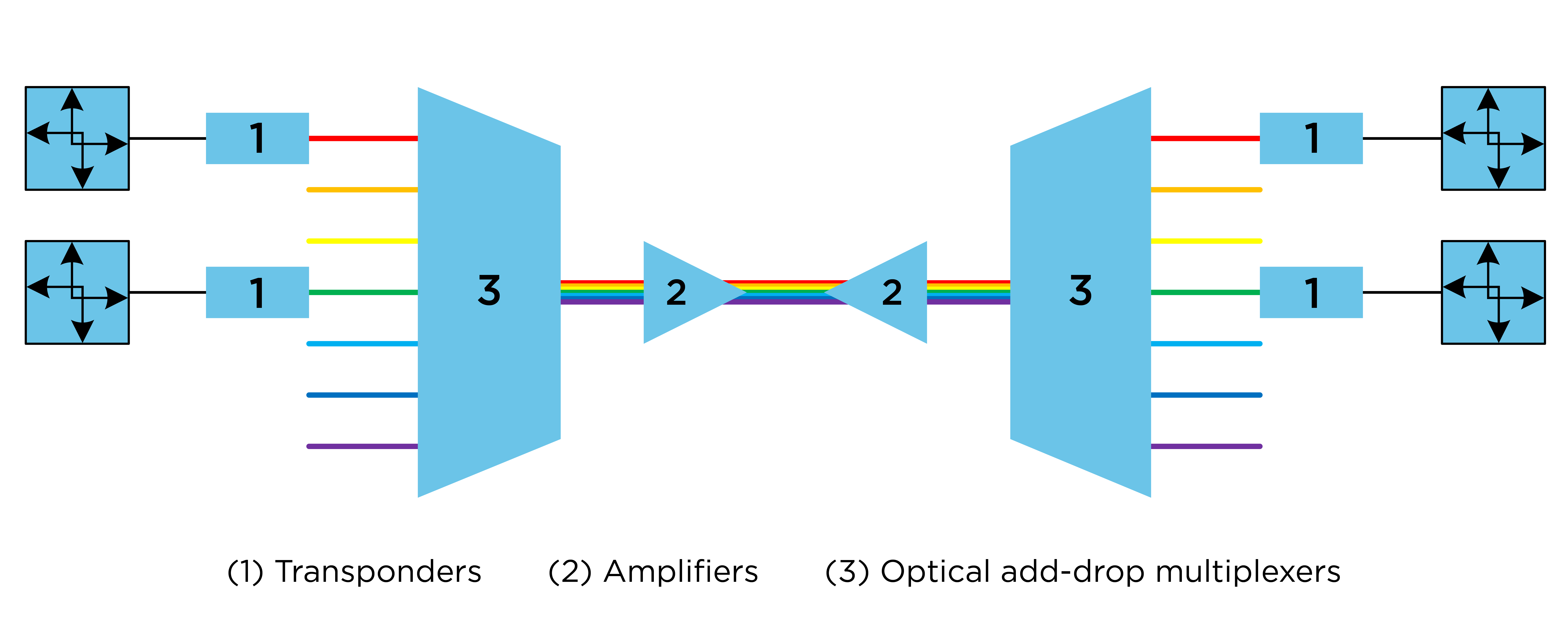
White Paper

Navigating the Data Highway: The Role of DWDM in Utility Communication Networks

DWDM technology allows utilities to upgrade their fiber-optic networks with a fast and efficient networking solution that can handle more data and enable better communication and operations.


In today’s world, data races like vehicles on a bustling digital expressway. The demand for faster and more efficient communication and data sharing is ever-present.

Enter dense wavelength division multiplexing (DWDM).

Utilities need to make informed decisions about their communications infrastructure. Having a clear understanding of how DWDM technology can address their needs, meet utility-specific requirements, and enhance operations is essential for utilities looking at the technology.


Read The White Paper

In today’s world, data races like vehicles on a bustling digital expressway. The demand for faster and more efficient communication and data sharing is ever-present.

Enter dense wavelength division multiplexing (DWDM).

Utilities need to make informed decisions about their communications infrastructure. Having a clear understanding of how DWDM technology can address their needs, meet utility-specific requirements, and enhance operations is essential for utilities looking at the technology.

The Case for DWDM

Utility networks have a growing need for connected operational technologies. The number of devices requiring communications, number of applications using the network and the associated capacity required to backhaul all this data is growing. Designed to increase capacity by orders of magnitude, DWDM is a form of wavelength division multiplexing (WDM) that supports complex network operations directly at the optical layer. DWDM can fulfill these requirements for growth within operational technology systems.

Many utilities own a private network to connect their various locations and often have redundant data or control centers where the data is collected. As the utility needs more real-time visibility into more of the grid to operate reliably, network capacity requirements must follow form. These requirements come from new regulations and the increased adoption of technologies including electric vehicle charging, renewable interconnects, battery storage and residential solar inverters.

As more applications use the network and the available individual fiber strands in the cables between locations are used, fiber capacity becomes a constraint. For older fiber cables, which typically contain fewer strands, this constraint is more common and may be compounded by individual broken strands or right-to-use agreements. New communications paths or increased capacity requirements must either build a new fiber path between the locations or consider multiple upgrades to transport router capacity. Opting to use more fiber to meet the demand can quickly balloon in scope as the need is typically doubled to create redundant paths on another cable for failover.

Utilities may have unique geographic service territory challenges as they build out their privately owned fiber networks as is the case in Figure 1. Similarly, a utility may not have a single contiguous service area and may need to cross territory owned by a neighboring utility to provide communications backhaul to devices. These critical long-haul connections often provide redundant paths to maintain the resiliency of the overall network. DWDM can help increase fiber utilization and provide the necessary reach for applications that may not otherwise have optics powerful enough to make use of these critical paths.

The combination of capacity needs, fiber path redundancy requirements and fiber availability constraints create a use case for DWDM. With DWDM, fiber strands can be leveraged more efficiently for increased throughput and increased span distances.

Figure 1: Building higher strand-count cables in some areas can be costly, due to logistics.

CLICK TO ENLARGE

DWDM relieves fiber constraints by allowing more applications to communicate over a single fiber pair and can send higher-capacity communications links over longer distances. While coarse wavelength division multiplexing (CWDM), another form of WDM, can resolve fiber capacity constraints, CWDM is subject to limitations that DWDM can overcome:

  • CWDM is a passive solution that introduces additional loss to any existing links planning to use the system. This does not solve the issue of long fiber spans.
  • CWDM requires the equipment sharing the fiber to use specialized optics intended for CWDM, which may or may not be available for a specific type of equipment.
  • CWDM optics are manufactured to use a specific wavelength that cannot be tuned. Tracking, ordering and installing these specific parts is done per-port for every device connected to the CWDM filters. This coordination may be especially difficult if one or more equipment vendors do not offer CWDM optics.

In contrast, the tasks of compensating for signal attenuation and coordinating wavelengths are handled internally to the DWDM system. This allows the applications sharing fiber strands with DWDM to communicate using lower-cost and more readily available optics in the end devices. Individual equipment manufacturers may not offer or support optics for other types of WDM, especially if the platform is nearing or at its end of life.

Where DWDM Fits

DWDM can be deployed in multiple ways to fit the needs of the utility network. A DWDM system can be as complex as an interconnected network performing optical layer routing across multiple nodes or as simple as a point-to-point link for long-haul communications. 

Utilities typically use DWDM to complement a higher-layer operational technology (OT) wide area network (WAN) that extends over a large geographic area and connects multiple local area networks (LANs). DWDM provides a lower transparent layer for systems such as IP/packet-based transport or SONET (synchronous optical network) to traverse. DWDM allows multiple networks and technologies to share physical fiber infrastructure while still providing separation in the form of wavelengths that maintain a physical barrier between each system.

DWDM systems that work in tandem with WAN systems often share an operations group managing the devices. Depending on specific needs, the DWDM system may be mostly static in nature and required changes are infrequent. 

While DWDM can alleviate congestion in large networks, it can be a complex system to maintain, depending on the design. Staffing and training at different levels in the organization is important to maintaining reliable operation. A utility DWDM system is typically used to backhaul high-capacity and long-haul links, so human error in operation will typically affect multiple applications in a
noticeable way.

Core DWDM Components

Design of a DWDM network requires understanding how each component functions and how DWDM will integrate into existing network operations. Ideally, a design will resolve problems without adding more complexity than needed with features that may or may not be helpful. 

A DWDM system is comprised of three main components as seen in Figure 2: transponders, amplifiers and optical add-drop multiplexers (OADMs). Beyond these three main components are additional components for equipment management and ancillary functions and features. The DWDM system is transparent to other OT devices that communicate through DWDM using standard optics.

Figure 2: DWDM components.

CLICK TO ENLARGE

Transponders

Transponders change the input wavelength of a received optical signal to an output wavelength that is appropriate for DWDM applications.

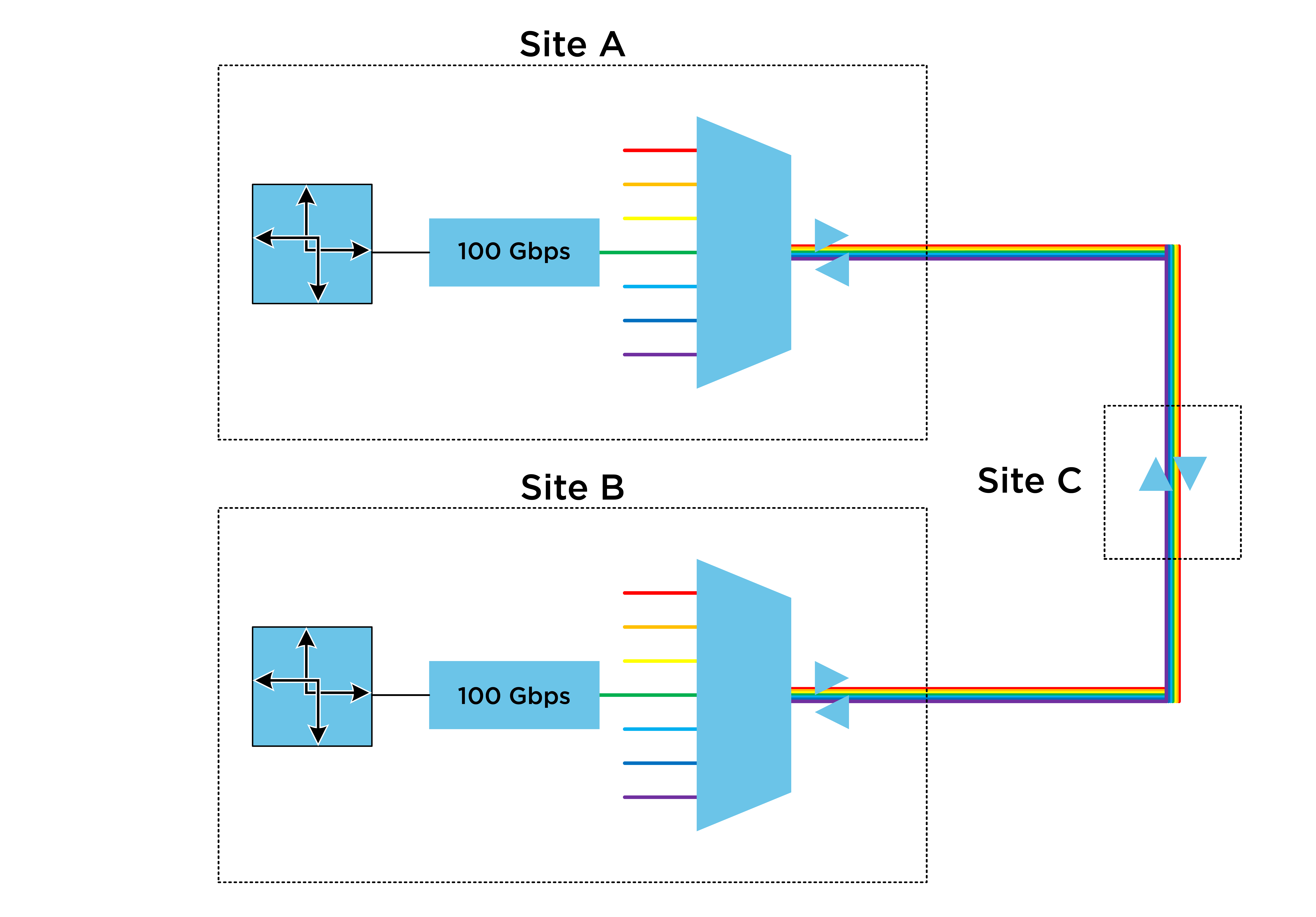
A DWDM system needs to convert conventional wideband gray optical signals into the colored optical signals of the DWDM domain. Signals in the DWDM domain are also referred to as wavelengths, lambdas or channels. A gray optical signal centered around a common wavelength such as 850 nm, 1310 nm, or 1550 nm is converted into a colored signal. The colored signal has a wavelength centered around a different frequency tuned to operate using a much narrower “dense” channel of optical spectrum.

The conversion of an optical signal allows multiple signals from end devices to be received at the same wavelength, such as 1310 nm, and multiplexed together as separate wavelengths on a single fiber. The incoming signals such as OC-48 SONET, OC-3 SONET, 10 Gbps Ethernet and 1 Gbps Ethernet are then transmitted across shared strands of fiber.

Transponder Capacity

DWDM systems allow for much greater capacity when compared to gray optics on a single pair of fiber. General trends for DWDM equipment move toward additional capacity and higher rate speeds without having to replace existing technology. Manufacturers often highlight methods to maximize throughput by more efficiently using available optical spectrum or expanding into additional spectral bands. The motivation for these methods is often intended for a scale that is beyond the needs of a utility operations network. Standard DWDM methods using fixed applications and the conventional C-band can still scale to handle capacities of terabits per second.

Because large carriers drive the market for DWDM equipment, utilities that use DWDM in their operations network are affected by market trends of carriers. Manufacturer trends are to move support away from lower-speed interfaces in favor of spectrally efficient line rates such as 100 Gbps, 400 Gbps and 800 Gbps. 

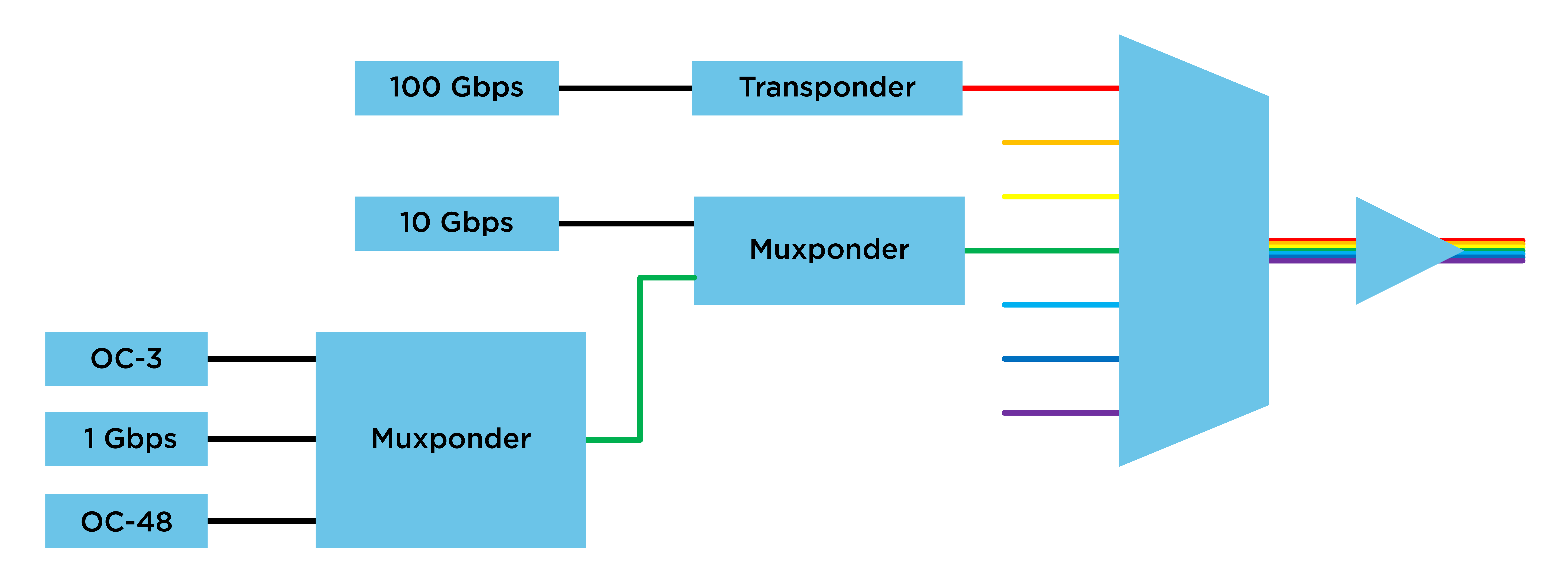
The sub-100 Gbps line rates, common in utility communications, can be multiplexed into a higher-speed DWDM signal. A transponder that takes in multiple lower-speed client connections and multiplexes them into a higher-speed line rate is known as a muxponder.

A muxponder can be used to map multiple OC-48 connections into a single 10 Gbps signal or multiple 10 Gbps Ethernet connections into a single 100 Gbps. Muxponders can also be cascaded to feed lower-speed signals into higher-speed line signals as seen in Figure 3. Common 1 Gbps and OC-3 signals can be multiplexed into a 10 Gbps signal and multiplexed again into a 100 Gbps signal. Using this method, lower-speed circuits can still seamlessly use equipment designed for higher-speed circuits more commonly found outside of the utility industry.

Figure 3: Cascaded muxponders.

CLICK TO ENLARGE

A factor driving manufacturers to discontinue support for lower-speed line rates is the use of coherent optics. At rates of 100 Gbps and above, modern transponders and pluggables now use coherent optics to manage chromatic dispersion with digital signal processing rather than dispersion compensating fiber. Correcting this issue with digital signal processing rather than a separate piece of hardware eliminates additional physical components from the DWDM system. Eliminating hardware reduces the footprint a DWDM system requires in a communications rack and removes extra connections and points of failure in the system.

Increasing Efficiency

Optical signals must overcome both dispersion and attenuation in fiber links. Attenuation in fiber links increases with distance and varies depending on the signal’s wavelength. DWDM transponders convert the client-side wavelength to a more suitable line-side wavelength for better amplification and lower attenuation. When multiple transponder signals are combined, they can share amplifiers optimized for their specific wavelengths.

Amplifiers

Amplification in a DWDM system is one of the primary benefits to a utility using DWDM. Amplifiers along signal paths provide the necessary reach for other OT network signals that may be expensive or impractical to regenerate by adding another WAN transport node or repeater. 

Amplification at the DWDM layer allows the client optical signals to reach distances not possible by gray optics alone. This is an advantage when connecting two nodes separated by long distances or when attempting to limit the number of locations where active equipment is required for repeating signals.

As seen in Figure 4, amplifiers can be classified into three categories depending on their location within the DWDM system:

  • Preamplifiers. Preamplifiers are positioned at the ingress of the DWDM node and strengthen optical signals after they have traveled through the optical fiber. By amplifying the signals at this stage, preamplifiers amplify signal power to levels that are appropriate for routing and filtering.
  • Post (booster) amplifiers. Post amplifiers are positioned at the egress of the DWDM node to boost signals before they undergo transmission through optical fiber. By boosting the signals at an early stage, post amplifiers help overcome signal degradation due to attenuation and noise. These amplifiers maintain signal integrity and strength throughout the network, enabling efficient and reliable data transmission over long distances.
  • In-line amplifiers. In-line amplifiers (ILAs) are a combination of both pre- and post-amplifiers located at a midpoint site. ILAs are separate nodes used to make a long fiber span feasible that otherwise would not be when relying on amplifiers at the end points alone. ILAs are typically less expensive nodes due to the lack of transponders or filters and ILAs can often be environmentally hardened. If there is a future need for DWDM at a midpoint site, an ILA may be advantageous for planned future growth. Using an ILA for planned future growth may allow less-expensive amplifier configurations to be used at the required endpoint sites.

Figure 4: Amplifier positions.

CLICK TO ENLARGE

EDFA and Raman Amplifiers

There are two different types of DWDM amplifiers based on the method of amplification.

  • Erbium-doped fiber amplifier (EDFA). EDFAs are the most commonly used amplifier type because they can amplify optical signals at any point along the signal path. Amplification is achieved by a pump laser exciting erbium ions, which transfer energy to the incoming optical signal. Equal gain across DWDM channels is not possible with an EDFA without the use of other mechanisms such as gain-flattening filters or channel-specific attenuation.
  • Raman amplifiers. Raman amplifiers use the principle of Raman scattering and use a pump laser in the reverse direction of the optical signal traveling through a fiber. Raman amplifiers require a minimum physical span of fiber to operate because amplification is spread across the physical fiber itself. This method provides flatter gain across DWDM channels and can achieve longer distances than by using an EDFA alone. A Raman amplifier is typically used for longer distances in combination with an EDFA and not deployed on its own. Raman amplifiers are more expensive and typically have additional safety considerations due to high optical output power.

Optical Add-Drop Multiplexers 

Any link that requires amplification in a DWDM system is likely to also benefit from the use of an optical add-drop multiplexer (OADM). An OADM increases the capacity of a single pair of fiber by providing the fundamental multiplexing/demultiplexing of the individual dense wavelengths.

Even with only one wavelength required when a DWDM system is designed, including a low-complexity OADM can provide some future benefits for minimal additional cost. Including an OADM in the initial design allows for future expansion or upgrade without any downtime of the existing connection. Multiple types of OADMs exist.

  • Fixed OADM. The simplest form of OADM is the fixed OADM (FOADM). A FOADM is a passive filter where each individual channel is broken out to fixed physical ports to add and drop channels. FOADMs fit well in simple point-to-point designs and in DWDM systems that will largely remain static without frequent addition or removal of DWDM channels. When using FOADMs at midpoint locations, a physical connection is required between FOADMs to pass channels from one fixed link to another. If many pass-through sites exist (such as on a ring) then this requires travel to each site for cleaning, end-face inspection and physical connections.

    While pass-through connections between FOADM links can be time- and labor-intensive, this effort is only required when a new line-side DWDM link is configured. Some of this additional physical effort can be reduced by combining the use of FOADM links with muxponders. A single higher-speed line rate can be physically cross-connected between locations. Any additional lower-speed client connections can simply be added to the originating and terminating muxponders.
  • Reconfigurable OADM. A reconfigurable OADM (ROADM) combines the passive filter of a FOADM with a wavelength selective switch (WSS) to enable optical routing. ROADMs are used to remotely configure pass-through connections, but passive filters are still required at sites where channels are added and dropped. A DWDM ring may be large enough or there may be frequent changes such that physically visiting every site to patch a channel through becomes cumbersome or unreasonable. In these cases, ROADMs can save costs to reconfigure the network because of the ability to make changes remotely.
  • Colorless ROADM. A colorless ROADM, sometimes referred to as a tunable OADM (TOADM), can replace both the ROADM and FOADM. TOADMs can avoid the use of fixed filters entirely because they can be tuned to add-drop any specific optical wavelength (color) on any port. Using TOADMs offers several advantages compared to using ROADMs:
     
    • TOADMs can interface directly with the line side of a transponder or muxponder. This removes the restriction from ROADMs, which must add-drop all wavelengths at a location.
    • TOADMs reduce the number of connection points required to convert a client signal into a DWDM signal. This can decrease the amount of rack space consumed and reduce points of failure.
    • Advanced DWDM architectures require the use of TOADMs. Using TOADMs can help to future-proof a DWDM system.

Prioritizing Resiliency

DWDM networks can expand upon the use of colorless ROADMs by using an architecture known as colorless-directionless-contentionless with flexgrid (CDC-F). The CDC-F architecture adds flexibility for making changes to the DWDM network, but network flexibility is often already designed into the existing operations network. Unless a utility has a need to manage a full-featured, high-capacity DWDM network in addition to an OT network, then pursuing a CDC-F architecture carries extra cost and complexity for what may be limited benefit.

Utility operations networks are usually built with resiliency in mind and reliability is prioritized over carrier-scale capacity. OT networks can provide service protection or restoration and a DWDM network designed to work with the OT transport systems can help provide a balance between capacity, resiliency and complexity.

Protecting services against a fiber break can be done at the optical layer with DWDM or at the electrical layer by rerouting traffic. Protection at the electrical layer is more flexible because protection at the optical layer uses additional hardware or wavelengths. In situations where reach is a primary concern, protection at the optical layer may be the only option.

Additional Considerations for Utilities

Utilities considering a DWDM system must also factor in other considerations such as integration capabilities and cost.

Optical and Routing Integration

A utility DWDM system is a subset of the main operations network. It often serves as a necessary transport component and may have separate management needs from the bulk of the operations network. However, the distinction between the DWDM system and other devices in the OT transport network is becoming blurred.

Routed networks use logical constructs in software for processing, whereas DWDM system configurations are highly dependent upon the optical hardware. In a DWDM network, a signal may cross between several different chassis as the signal is amplified, filtered and converted between DWDM and wideband channels.

A trend in optical networking is to move the transponder function of a DWDM system directly into the optics of routers in some OT transport networks. This blending of functions underscores the importance of understanding both systems.

DWDM Costs

Gray optics with long-haul capabilities and high bit rate can potentially be more costly than a simple DWDM system with a fixed OADM. This is especially true if the long-haul, high-speed link needs to be repeated anywhere along the path.

Core network links between data centers often require more expensive equipment to support higher bit rates. These higher capacity links may require additional equipment to be installed in harsh environments due to the distance limitations of the traditional pluggable optics in a single device. These environments limit what equipment is suitable for that location. DWDM can be used in this case to reduce the number of intermediate nodes and avoid unconditioned environments altogether.

The example, as seen in Figure 5, is a 100 Gbps connection required to connect two utility data centers. A DWDM solution would allow the 100 Gbps connection to use lower-cost short-reach optics at each end. If any additional amplification is required, an environmentally hardened ILA could be added at a midpoint site.

Figure 5: Data center link.

CLICK TO ENLARGE

Getting More Out of Your Operations Network With DWDM

Most utilities have the responsibility to operate and maintain reliable communications backhaul for a growing number of applications on an operations network. Utility operations networks may face challenges of fiber capacity, throughput limitations, long fiber paths, or a combination of challenges. A DWDM system can resolve these challenges.

The goal for a utility DWDM system is to support operations and prioritize reliable transport rather than carrier-scale traffic capacity. It can be a daunting effort to determine which parts of a DWDM system are required for any specific need. It can be equally daunting trying to maintain familiarity with DWDM equipment and what roles the individual components play within the larger operations network. Having a greater understanding of modern components and applications for specific use cases will allow utilities to focus on technologies that fit the needs of their networks.


Authors

Matt Kitchen

Senior Electrical Engineer

Ethan Koch

Staff Electrical Engineer