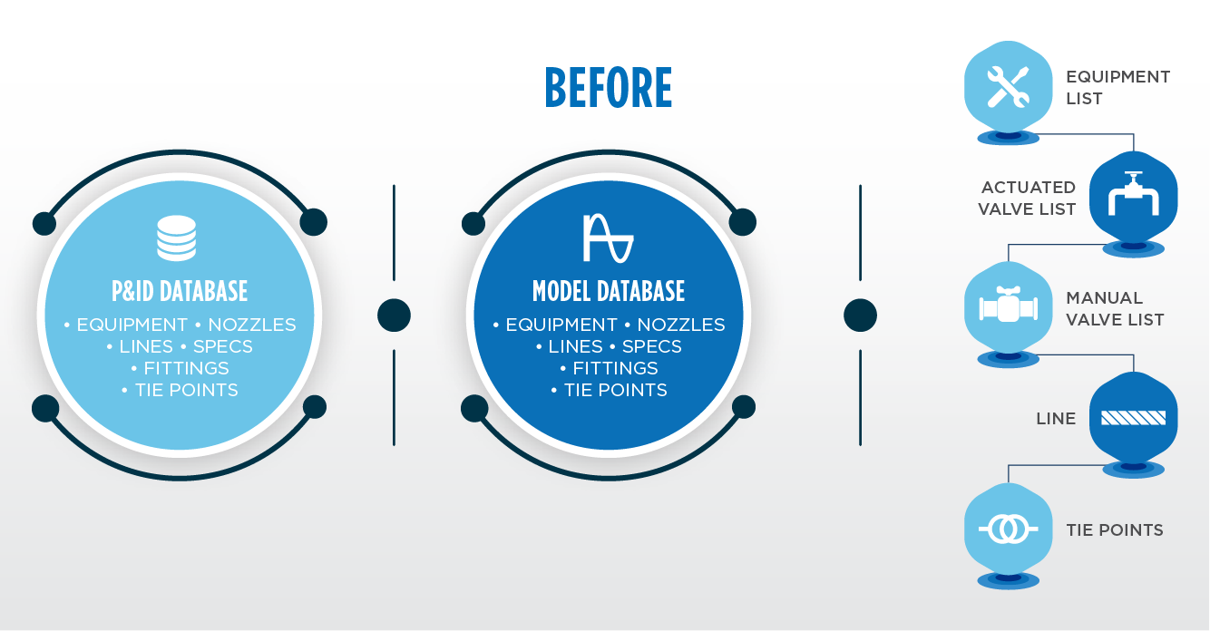
MAKING DATA INTELLIGENT
Perhaps 20% of the data intelligence design teams require is already incorporated within existing engineering tools. Innovative EPC firms are developing the remaining 80% by building advanced capabilities into industry standard software.
BUILDING ADDITIONAL DATA FIELDS INTO THE SOFTWARE
EPC teams that specialize in data intelligence begin each project by creating an appropriate data structure during the engineering design process. Although the data itself may not be available until much later, teams can work through the details of procurement and construction to identify all necessary data fields. Then those fields are built into the design software suite.
For instance, to create an effective and constructable tie point list, EPC teams need to list the P&ID, plan and line number (isometric), as well as comment on the work to be performed. These fields are added during project setup to be filled as design continues and populate the construction tie-in list automatically.
LINKING DATA FOR RELATED COMPONENTS
After the necessary fields are established in the software, relationships are created between them. All data is linked back to its parent component, so data only needs to be entered once. Additionally, the data contained within each component is customized to create relationships between related data that wouldn’t necessarily be linked otherwise. For example, the system might be designed to require that every instance of a particular valve acquires the related line information, including size, specification and the product going through the pipe. When a valve is placed, it is forced to have the same size as the line that it is placed on. This safeguards quality and provides a second annotation to identify any errors in the line work.
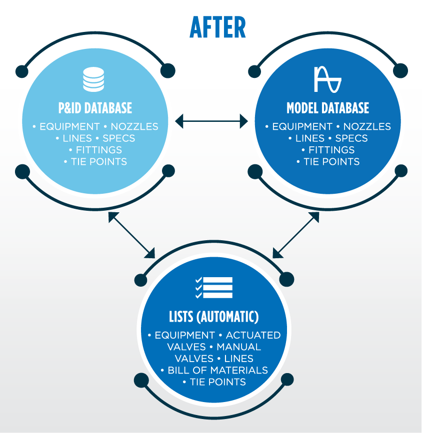
This approach connects components within the P&ID and across deliverables, meaning data in the 3D model can be acquired automatically when the design team begins that stage.
AUTOMATING DATA UPDATES ACROSS DELIVERABLES
As data becomes available, it is entered into the prepared fields and verified. Then it is pushed automatically to all its child components. This drives the creation of line, equipment, tie-point and other lists. For example, if “P100” has been entered in the “provided by” and “installed by” data fields within the design software suite, it can automatically filter all equipment by “P100” and populate a list of components to be provided by that P100 contract. An equipment list for each contract on the project can then be issued with minimal effort and high accuracy.
When data is populated in the P&IDs, it is acquired into the 3Dmodel and the corresponding plan sheets are updated with the same information. Line annotations (including size, service, specification and line number) and valve annotations (such as tag, size and specification) are populated automatically. Isometrics, line and bill of material information also is generated automatically based on the data contained within the 3D model.
If the design team updates a piece of data, that change is carried throughout all documents automatically. Validation checks can also be run to identify discrepancies between deliverables. When an error is detected, it can be corrected in one place, with updates pushed to all deliverables. This allows the production of highly accurate construction packages — including P&IDs, 3D models, isometric diagrams and lists — faster and with fewer engineering resources. Figure 2 shows improved acquisition and sharing of data to form a connected deliverable set.

