Understanding the Feasibility and Design of Horizontal Directional Drilling

BY Lalit Chilana, PE

Evaluating the feasibility of the horizontal directional drilling technique can be a challenge for utilities and pipeline operators. A thorough survey of the site and surrounding areas and understanding of the construction challenges can provide transparency and enhance efficiency of the HDD design process.

Read The White Paper

Horizontal directional drilling (HDD) is a trenchless technique used for installation of pipes, conduits and cables along a specified route. Directional drilling machines and ancillary equipment are used to precisely drill along the proposed alignment and to help utilities get from one point to another with little or no disturbance to the existing infrastructure above and below the surface.

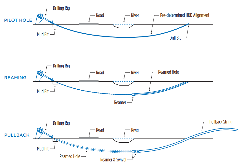
HDD installation is a multistep process:

  1. Pilot hole: This is the perhaps the most crucial step for successfully installing an HDD crossing. The pilot hole requires drilling along a carefully designed path. The drill bit is monitored and tracked in real time to minimize any deviation from the proposed path and to make adjustments as needed.
  2. Reaming: The second step consists of employing a tool called reamer to enlarge the pilot hole to a final diameter greater than the product pipe. The type and size of the reamer depends on numerous factors, such as geological formation, drilling mud and product pipe diameter. Typically, an overcut of 12 inches or 1.5 times the diameter of the product pipe is used by the contractors.
  3. Pullback: The final step in the process entails pulling the product pipe through the reamed borehole, which involves attaching the fabricated pipe string to the drill pipe using a swivel and a pullhead. It is recommended to complete the pullback step without pausing or stopping to avoid the pipe getting stuck within the borehole because of drilling mud settling and solidifying.

TND_HDDDesignBestPractices_17297 WP Fig1

FIGURE 1: HDD process.

HDD is primarily used for installing utilities (electrical, natural gas, oil, water and wastewater) across rivers, large water bodies, roads, railroads, congested utility corridors and other sensitive areas where conventional trenching poses challenges. This method has higher upfront costs (material and installation) compared to the conventional pipe installation technique, but it is more common in areas where trenching can be an undesirable option or might be prohibited.

FEASIBILITY EVALUATION

Given the higher total installed cost for HDD, a feasibility evaluation can help assess the suitability of using HDD and demonstrate the value proposition. There are several parameters that are considered while evaluating the feasibility of any HDD project.

Installation type: Understanding the type of installation, whether it is a transmission or distribution line, helps in defining the pipe size and specification. Transmission lines typically require mid or large size pipe diameter (typically 12 inches or larger), whereas most distribution lines use a smaller size pipe diameter (typically less than 12 inches). A steel pipe is the common carrier pipe for oil and gas projects; however, polyethylene (PE) or PVC pipe is often preferred for electric, water and wastewater utilities.

Obstructions: This involves identifying any significant and sensitive obstructions being crossed, such as streams, rivers, water bodies, wetlands, environmentally sensitive areas, railroads, major highways or existing utility corridors. Some of the obstructions, such as railroads, navigational waterways or levees, prohibit any trenching and mandate the use of the HDD technique. Often, several obstructions are grouped in a single crossing to optimize the design.

Geology: Geological formation is the biggest factor playing into the success of the project, and it can derail the project budget and/or schedule regardless of an appropriate design. Therefore, it is imperative to identify the local geology using available published data and consider how it would impact the HDD in the initial stages. Geological formation varies from place to place, for example, in the northeastern states of the United States, bedrock is prevalent, whereas in Southern states, alluvial deposit is more common near the coast.

Constraints: It also helps to know various constraints, such as accessibility issues, workspace issues or permitting-related restrictions that could affect the HDD installation.

Noise mitigation: This is a unique concern that is often overlooked and can have an adverse impact on the project budget and schedule if not evaluated early in the design stage. Surveying the surrounding areas, evaluating and understanding the magnitude of the noise generated from the site and potentially installing temporary sound barrier walls can drastically ease the noise levels and assist in adhering to the local noise ordinances.

A comprehensive feasibility report is prepared after evaluating all the concerns and a recommendation is made to either proceed into the detailed design phase or evaluate an alternate route for the pipeline installation.

DETAILED DESIGN

After the HDD design feasibility evaluation is performed and the route is selected, the process moves into the detailed design phase. There are some additional factors that are considered in the detailed design stage.

Site conditions: Reconnaissance is performed to understand the physical aspects of the proposed crossing and identifying site features such as:

  • Subsurface: Foundations, underground structures and archeological sites.
  • Surface: Federal and state lands, reservations and nearby existing structures.
  • Overhead: Power lines and overpasses.

Workspace and accessibility: Providing adequate space for contractors is important to allow them to work efficiently and safely at the site. Typically, the diameter of the product pipe and length of the crossing determines the size of the drilling rig, drilling mud recycling system and ancillary equipment. Usually, a large entry and exit workspace is required for larger HDD drills, but a smaller entry and exit workspace is sufficient for medium- to smaller-size drills. The pipe stringing area must be appropriately sized so the contractor can prepare the pipe string in one section. This eliminates the necessity of stopping the pipe during pullback to perform a weld. Figure 2 provides more information on the recommended workspaces. Access roads should be identified and evaluated in the early design stages for proper ingress/egress at the entry and exit sites. Any necessary upgrades or modifications should be proposed for the access roads to allow the construction equipment to navigate safely.

TND_HDDDesignBestPractices_17297 WP fig 2

*Pipe stringing area should be designed to avoid any point of inflection (PI) or curvature. In case of a PI, a temporary workspace should be acquired to prepare the pipe string in a straight section.

FIGURE 2: Best practices for HDD workspace.

Permits: It is vital to prepare and apply for the necessary permits while designing the HDD to avoid any construction delays. A drill path across environmentally sensitive features might take several months to get approval, so it is advisable to start coordination with the jurisdictional authorities in the early stages of the HDD design.

Geology: During the feasibility stage, geological information collection is typically limited to published data from previous projects or online resources such as U.S. geological maps or USDA soil survey. However, detailed design requires a site-specific geotechnical investigation to gather the required soil information for designing the crossing while understanding the risks posed by geology. This investigation requires preparing a geotechnical scope of work, which determines the number of soil borings including their location and depth, geotechnical investigation methods for various soil types, and required testing parameters for completing the HDD design. Figure 3 highlights some of the best practices related to the soil boring location, depth and offset from the proposed alignment.

TND_HDDDesignBestPractices_17297 WP fig 3

FIGURE 3: Best practices for soil boring location and depth.

The project design should take into consideration when bedrock, coarse/granular material, including any gravel, cobbles or boulders, is found during the geotechnical investigation.

  • Bedrock should be carefully analyzed to understand the important characteristics, such as, degree of weathering, fracture planes, unconfined compressive strength and cerchar abrasiveness index (CAI) to determine the overall impact on the project. An extremely weathered and fractured rock is susceptible to drilling fluid losses and steering issues. Also, a higher strength rock will be difficult to penetrate and would require frequent changing of the drill bits and tooling. This would result in higher installation cost and duration.
  • Coarse or granular material can have larger void spaces, presenting an opportunity for the drilling fluid to migrate during the drilling process. This can result in drilling fluid losses during the installation and an increased potential for an inadvertent return.
  • Any gravel presence, especially of larger particles (greater than ¾ inch) and higher quantities (greater than 30%) can present steering challenges and increase the risk of bore hole collapse.
  • Extremely large particles such as cobbles and boulders are challenging to drill through and can cause the drilling tools to wear out prematurely.

Geometry: The preliminary geometry is refined to adjust the natural ground profile and HDD alignment after a topographic survey is performed. The soil boring logs from the geotechnical investigation are also incorporated into the HDD drawing to determine the HDD elevation with respect to the soil stratigraphy.

SOME OF THE GUIDELINES TO FOLLOW WHILE DESIGNING HDD GEOMETRY:

  • Radius of curvature on entry and exit side = 100 x pipe nominal diameter
  • Entry angle = 8 to 15 degrees
  • Exit angle = 6 to 14 degrees

It is recommended to use shallower angle on the exit side for the bigger pipe diameter to ease the product pipe handling and aligning with the bore hole.

Inadvertent return (IR) analysis: The IR is defined as an unintentional migration of drilling liquids to the surface during the drilling process. An IR analysis is performed to identify and eliminate IR risks across the crossing. Final design adjustments are made based on the results of the IR analysis, such as increasing the depth or choosing a specific soil strata for the HDD alignment to pass through to minimize the risk of an IR.

Stress analysis: A stress analysis is performed to determine whether the proposed pipe can withstand the installation and operational stresses while complying with the code requirements. Stresses are typically calculated using the following standards and references:

  • Installation of Pipelines by Horizontal Directional Drilling Engineering Design Guide, PR‑277-144507-Z01.
  • ASTM F1804-08: Standard Practice for Determining Allowable Tensile Load for Polyethylene (PE) Gas Pipe During Pull-in Installation.

CONCLUSION

The success of any HDD project largely depends on the technical feasibility of the crossing. However, the economical and contractual aspects are equally important to determine the overall impact of utilizing HDD technique on the project’s budget and schedule.

Technical feasibility entails a thorough analysis of design and engineering factors such as installation type, obstructions, geology, geometry and accessibility of the project site. In contrast, determining economic feasibility requires establishing a baseline cost to install the crossing using the HDD technique. A comparative cost analysis is performed to weigh the total installed cost of the proposed crossing against other feasible methods to determine the overall impact on the project cost. Contractual feasibility requires determining the risks associated with the HDD installation and providing the utility or pipeline operator an opportunity to address those risks prior to construction.

Usage of the HDD technique has grown tremendously in the last two decades, especially for installing pipes and cables underground where open trenching cannot be used. However, the answers to feasibility questions demand extensive research to accurately assess the technical and economic aspects of the project to making cost-effective and defensible decisions.

PROJECT STATS

CLIENT
University of Utah

LOCATION
Salt Lake City, Utah

COMPLETION DATE
Spring 2017

CHALLENGE

Established by the U.S. Department of Energy, the Better Buildings Challenge (BBC) program encouraged interested parties to identify savings strategies and reduce energy consumption through facility modifications. The University of Utah signed up for the program and established a revolving savings program internally to fund the project with an overall goal to reduce campus energy use by 20% by 2020.

The university needed a team to identify and quantify energy use along with categorize high energy utilization index (EUI) buildings on their campus. Very quickly, the buildings with high EUIs were identified as the laboratories on campus. Burns & McDonnell could then focus on evaluating energy measures and strategies around the laboratory environment. The BBC’s goal was to not only reduce the energy footprint of campuses, but also to provide economic savings while universities maintained effective facility use. Before any facility modifications could be made to reduce the university’s energy usage, facilities needed to undergo an energy audit to identify inefficient levels of energy consumption occurring around campus.


$1.2M

DESIGN FEES
 

475K

SQUARE FEET RETROFITTED
 

25%

VERIFIED ENERGY SAVINGS


33361_lalit_chilana_2020_sq_cl_01_small1

Lalit Chilana, PE

Senior Pipeline Engineer

  Connect on LinkedIn

Interested in learning more?

DOWNLOAD WHITE PAPER

Send Us a Note