White Paper

A Road Map for Battery Energy Storage System Execution

Grid-scale battery energy storage system (BESS) installations have advanced significantly, incorporating technological improvements and design and packaging improvements to enhance energy density, safety and integration with renewable energy sources. Successful execution of BESS projects requires understanding the nuances of the improvements and adapting system design and installation accordingly.


The Beginning of our Journey: Modularity and Practicality

Integration of energy storage products begins at the cell level and manufacturers have adopted different approaches toward modular design of internal systems, all with the goal of improving manufacturing efficiencies, reducing maintenance time and improving operational reliability.

In practice, the smallest unit of a BESS site that typically remains operational and under load during maintenance or inspection is the purpose-built enclosure, which houses the batteries. This approach is driven by several factors, including electrical safety considerations, the training and experience of facility operations staff, and the architecture of the control systems.

When designing a BESS facility, it’s important that maintenance is considered and that the system offtake agreements, system sizing, facility layout, electrical connections and protection design all consider planned maintenance frequency and required isolation points. The design needs to permit maintenance activities to continue safely while the facility remains available to respond to grid demands.


Read The White Paper

The Beginning of our Journey: Modularity and Practicality

Integration of energy storage products begins at the cell level and manufacturers have adopted different approaches toward modular design of internal systems, all with the goal of improving manufacturing efficiencies, reducing maintenance time and improving operational reliability.

In practice, the smallest unit of a BESS site that typically remains operational and under load during maintenance or inspection is the purpose-built enclosure, which houses the batteries. This approach is driven by several factors, including electrical safety considerations, the training and experience of facility operations staff, and the architecture of the control systems.

When designing a BESS facility, it’s important that maintenance is considered and that the system offtake agreements, system sizing, facility layout, electrical connections and protection design all consider planned maintenance frequency and required isolation points. The design needs to permit maintenance activities to continue safely while the facility remains available to respond to grid demands.

Successful BESS project execution requires a systematic approach that coordinates multiple disciplines, stakeholders and technical requirements. The following road map (Figure 1) illustrates the key phases and critical decision points that define successful BESS development from initial concept through operational deployment.

Figure 1: A BESS project development road map. A systematic approach to successful project execution requires coordination across multiple phases, from initial market analysis through commercial operation, with critical decision points and stakeholder engagement throughout the development life cycle.

CLICK TO ENLARGE

A Fork in the Road: Functionality and Ancillary Services

BESS installations provide a wide range of grid support services. However, depending on the market and the terms of the offtake agreements, only the system’s ability to deliver power (measured in MW) and store energy (measured in MWh) may generate meaningful revenue. For this reason, it’s important that any ancillary services that are required or desirable be included in the fundamental definition of the project, including the selection of BESS technology. These requirements can heavily influence balance of system (BOS) design.

In many regions and for numerous projects, IEEE 2800 is increasingly being adopted in place of IEEE 1547 to define the expected performance of BESS installations when connected to the grid. These standards play a key role in shaping the performance requirements and configuration of the inverters or power conversion systems used. However, the desired ancillary services can have broad impacts on the chosen storage technology as well.

For example, a grid-connected BESS using inverters or power conversion systems that meet IEEE 2800 standards can respond to frequency and voltage deviations while being dispatched during the charge or discharge cycle. However, providing fast frequency response or remaining connected and providing grid stabilization on a continuous basis, such as in the case of a microgrid, is an entirely different application.

One such specialty service requiring a bottoms-up retooling of typical designs is grid restoration or black start capability. A BESS can provide power to restart critical grid infrastructure following a blackout, reducing downtime and enhancing grid resilience. One of the major advantages of a BESS in black start operations is the rapid response time. Unlike conventional power plants that require time to warm up and synchronize with the grid, a BESS can begin discharging energy within milliseconds, providing crucial rapid response for grid restoration efforts.

Because of this, a BESS can either be utilized to restore critical services directly, or as a first step in grid restoration, providing initial power to start larger gas turbine-generators. Design for this application requires careful coordination of the loads, restoration sequence and BESS capabilities. An optimal system needs to be sized to carry the required load during restoration efforts and have additional margin to permit it to regulate voltage and frequency within tolerable limits for the loads. BESS installations also need to have sophisticated controls to adapt the response to the conditions as the system restoration sequence progresses. Finally, a BESS and BOS need resiliency incorporated into the design that considers the possible causes of the blackout conditions, as well as potential standby time that may be required for transmission operators to make decisions and dispatch resources necessary for grid restoration.

Navigation and Orientation: Plant Controls and Energy Management

The design of the power plant controller (PPC) and energy management system (EMS) is integral to the performance of a BESS. Selection of the PPC and EMS, from hardware to configuration, requires special attention to achieve the desired objectives and operational profile. There are key differences between a PPC and EMS. While it is possible for one system to fill both roles, in practice there are frequently two or more systems that must work together to provide complete controls for a BESS.

An advanced EMS incorporates data from the battery management system (BMS) to provide real-time tracking of key operational parameters such as state of charge, temperature, voltage and state of health. This continuous monitoring is essential for optimizing use of the facility, enabling proactive maintenance, protecting the health of the batteries for long-term performance and maintaining energy balance across the site. EMS also can provide market participation packages allowing facility owners to select when and how to automatically dispatch their batteries to make economical use of the batteries’ capabilities.

An advanced PPC allows for sophisticated closed-loop voltage and frequency control, coordination of multiple generating sources from different original equipment manufacturers (OEMs), and management of on-site energy use, including charging batteries from renewable sources and reserving energy for required ancillary services.

Regulatory and Standards Compliance Challenges

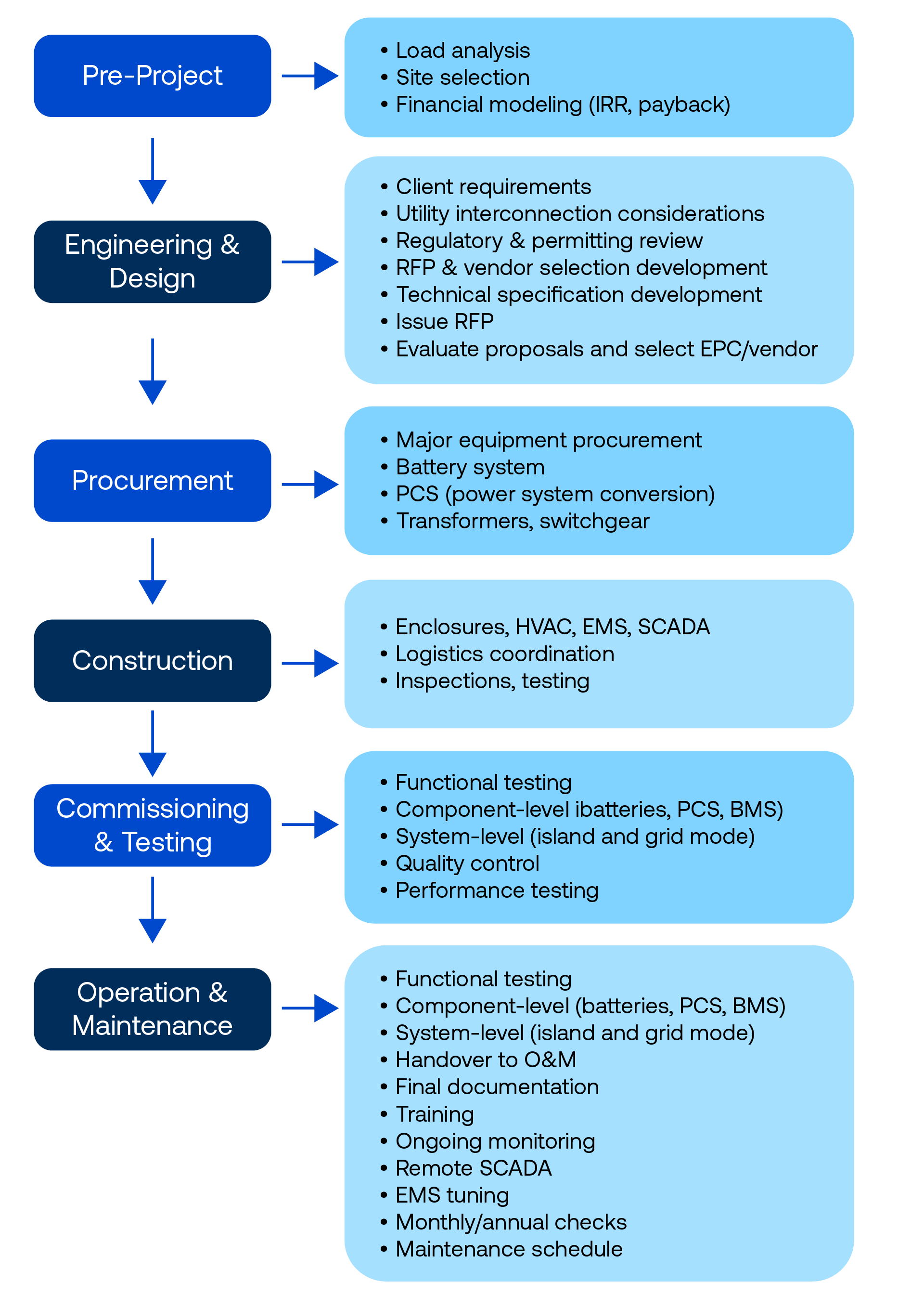
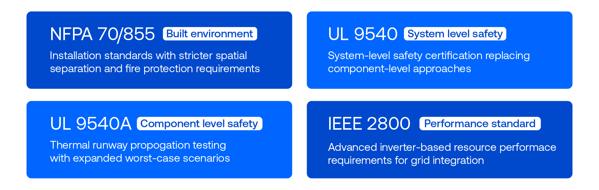
As the deployment of BESS installations accelerates, safety and interoperability standards are evolving rapidly to address emerging risks and operational complexities. Updates to key energy storage system codes and safety standards, particularly NFPA 855, UL 9540, UL 9540A and the expanding adoption of IEEE 2800, is reshaping the landscape for system developers, integrators and asset owners. While these standards are critical for safety, reliability and grid integration, they also pose challenges that must be carefully navigated to enable scalable and cost-effective BESS deployment.

NFPA 855, the Standard for the Installation of Stationary Energy Storage Systems, is increasingly being incorporated into adopted local Codes and Standards across the United States. However, one challenge can be variability in interpretation by authorities having jurisdiction (AHJ), who retain broad discretion in enforcement. Inconsistent application of NFPA 855 across municipalities can lead to unpredictable permitting timelines and redesigning cycles that increase both cost and risk.

UL 9540, the Standard for Safety of Energy Storage Systems and Equipment, has undergone recent revisions that place a stronger emphasis on system-level safety rather than just component-level certification. Manufacturers who previously certified individual components must now demonstrate the integrated system’s ability to perform safely under a wide range of fault conditions. This more holistic approach to safety is essential and ultimately leads to greater certainty of outcomes for project executions, but in the near-term results in additional challenges for OEMs seeking to release new products or determining whether to recertify existing products. It is critical for projects moving forward that execution teams understand that the International Fire Code (IFC), NFPA 855 and NFPA 70 (the National Electric Code) require energy storage systems to be listed, and that UL 9540 is the listing standard applicable. Closely linked to UL 9540 is UL 9540A, the Test Method for Evaluating Thermal Runaway Fire Propagation in Battery Energy Storage Systems. This test method is essential for understanding a BESS’s behavior under thermal abuse conditions. Recent updates to UL 9540A protocols include expanded worst-case testing scenarios, such as initiating multiple cells, testing damaged modules or simulating compromised enclosures.

UL 9540A by design does not provide a clear pass/fail metric; instead, these results generate data that must be interpreted by AHJ and fire safety consultants. The lack of a standardized interpretation framework leads to variable outcomes depending on local jurisdictional preferences, complicating project planning. Additionally, the cost and duration of conducting full-scale UL 9540A tests adds a significant cost — often exceeding hundreds of thousands of dollars — which can be prohibitive especially for smaller developers or novel battery chemistries. Revisions are underway to UL 9540A to define the expectations for large-scale fire testing. This test aims to replicate worst-case scenarios, such as full thermal runaway propagation within a battery rack, and evaluate the effectiveness of fire barriers, suppression systems and overall system resilience. Large-scale testing typically involves initiating failure using techniques such as overcharging, external heating or nail penetration, then observing system response in terms of temperature rise, gas generation, flame propagation and structural integrity. The outcomes of these tests provide actionable insights into how fire spreads within a system, the time frames involved and whether mitigation strategies effectively contain the incident.

IEEE 2800 defines the performance requirements for inverter-based resources (IBRs) connected to the bulk electric system. BESS assets are expected to provide grid services, including voltage regulation, ride-through capabilities, frequency response and support during system disturbances. Meeting these performance benchmarks requires advanced inverter technology and sophisticated control algorithms.

Validating IEEE 2800 compliance requires more sophisticated modeling and simulation, as well as additional commissioning steps, which must be considered when developing project timelines and commissioning plans.

The evolving standards have significantly improved the reliability and safety of BESS installations but require more understanding and coordination for correct implementation. Successful navigation of regulatory requirements for a given jurisdiction requires a proactive compliance strategy, careful selection of technology and system design, and early engagement with engineering and safety specialists. Regulatory standards at a glance are outlined in (Figure 2).

Figure 2: Regulatory standards at a glance that impact BESS development. The convergence of safety, installation, testing and grid integration standards creates a complex regulatory landscape requiring careful navigation and early compliance planning.

CLICK TO ENLARGE

Safety Considerations for BESS Installations

As BESS installations continue to scale in both size and application, especially with the adoption of larger-format lithium-ion cells, safety considerations have become even more paramount. The inherent risk of thermal runaway and cascading failures in these systems necessitates a multilayered safety approach that incorporates advanced detection technologies, includes explosion prevention strategies and validates rigorous large-scale fire testing.

Safety starts at the cell level, and in systems utilizing larger lithium-ion cells, explosion prevention becomes particularly challenging due to the higher volume of combustible electrolytes present in each cell, leading to increased combustible gas in the event of thermal runaway. To address this, cell design is evolving with improved safety features such as advanced separators to mitigate internal shorts or overcharging events.

Within battery modules, thermal barriers and heat sinks are implemented to slow or prevent thermal propagation. At the system level, active cooling methods such as forced air or liquid cooling help manage heat buildup during both normal operation and fault conditions. Most utility scale systems today utilize liquid cooling due to reduced auxiliary power requirements, enhanced efficiency, and most importantly because of improved temperature balancing across the cells in an enclosure.

Detection does not prevent thermal runaway, but it is critical to inform first responders, permit isolation, and aid in preventing catastrophic failures in BESS installations. Modern BMS are equipped with sophisticated sensors that continuously monitor key indicators such as voltage, current and temperature. These sensors are crucial in identifying and preventing abnormal conditions that may precede thermal runaway.

If a thermal event occurs, some systems incorporate gas detectors that can identify the presence of hydrogen or volatile organic compounds such as ethylene and methane. All systems are required to have a means of explosion prevention to deal with the possibility of accumulated gases in the enclosure. The most common approaches to this currently in the market include active ventilation, deflagration panels and proprietary systems to eliminate the gases as they are produced. The goal with all of these systems is first to prevent thermal runaway, and if it occurs to prevent the accumulation of explosive mixtures of combustible gases.

One hot topic in the industry is the potential negative effects of gases released in a thermal runaway event and how this informs immediate emergency response and long-term safety planning. Thermal runaway releases a complex mixture of gases, including hydrogen fluoride (HF), carbon monoxide (CO), carbon dioxide (CO₂), hydrocarbons and metal oxides, many of which are acutely toxic or flammable. To characterize these emissions, detailed plume analysis can be conducted using both empirical testing and computational tools such as computational fluid dynamics (CFD) and the fire dynamics simulator (FDS) developed by the National Institute of Standards and Technology. These models simulate gas dispersion within enclosures and in open environments under various ventilation and weather scenarios, providing critical data on concentration levels, dispersion distances and the potential for secondary hazards such as explosions or toxic exposure. This information feeds directly into risk assessments that inform the design of ventilation systems, sensor placement, emergency response protocols and evacuation planning.

As the deployment of BESS installations grow globally, continued investment and proactive efforts like these from industry leaders will be beneficial for public safety, safeguarding infrastructure and enabling the reliable integration of renewable energy resources into the grid. These efforts are sometimes necessary to provide confidence to local stakeholders in the planning for a given project.

Bringing a BESS Installation Online: Testing and Commissioning

The most sophisticated design in the world will not function correctly if there are no effective means for validating the installation and performance in the field. The testing and commissioning process is a critical stage for capturing potential errors and omissions from earlier stages of the project, as well as implementing improvements for performance (See Figure 3).

Figure 3: Equipment testing and system electrical integrity represent the fundamental starting point for a BESS installation.

CLICK TO ENLARGE

There are many integration and performance tests that should be considered when completing a BESS installation, including:

Load testing: Demonstrating the ability of the system to respond and provide contracted power and energy under all expected conditions requires careful planning and structuring of the tests, as well as coordination with transmission operators to thoroughly test the system.

Detection and communications: Validation of individual sensors and their calibration, integration into the master detection and annunciation schemes, and functional testing to verify any system actions such as activation of local indication or suppression systems if they exist is critical. The system performance and annunciation also need to be checked against the information available to first responders so that the information provided is clear and accurate. Many of these sensors are addressable, meaning each sensor has a unique identifier and can communicate specific data to the central monitoring system, allowing operators to pinpoint the exact location and nature of an issue. The use of addressable sensors supports centralized control, real-time monitoring, and integration with supervisory control and data acquisition or EMS, thereby improving situational awareness and system reliability.

Final safety checks: Before full system deployment, thorough safety checks are conducted for compliance with safety standards and to mitigate potential hazards. These checks include evaluating fire suppression systems, battery temperature controls, electrical connections and emergency shutdown protocols.

Integration with renewable sources: During commissioning, it is imperative to validate the PPC’s capability to manage the integration of variable renewable energy sources such as wind and solar. The PPC must provide precise active and reactive power closed loop control, stable response to system imbalances, and strict adherence to NERC and ISO requirements. This includes exhaustive testing of controls and responses to verify that systems operate reliably under real grid conditions. Confirming these capabilities is essential for regulatory acceptance, grid-code compliance and long-term system operability.

Commissioning of electrical protection systems: Rather than simply testing relays and downloading as-left settings, commissioning processes need a systematic approach to verification of transfer trip schemes, maintenance, arc-flash reduction, communications based tripping schemes and any custom protection logic.

Safe and Cost-Effective Delivery Calls for a Trusted Partner

Balancing performance and cost are essential to the success of a BESS facility. A well-coordinated and comprehensive design should align with project objectives while identifying the most cost-effective approach. However, successful execution goes beyond the technology selection and design and requires thoughtful consideration of all aspects of the project from early stage permitting through commissioning. Bringing all the disparate technologies, disciplines and service providers together to achieve a cohesive and effective project approach and an efficient and safe operating facility is no small task. But it is a journey that can be taken one step at a time and is the most enjoyable when taken with a trusted partner who has traveled the road before.


Authors

Megha Bhardwaj

Senior Electrical Engineer

Josh Crawford

Energy Storage Technology Manager