KEY FACTORS FOR SUCCESSFUL SOLAR CONSTRUCTION

BY Russ Gentemann AND Grant Reasor

With PV module costs dropping, decarbonization efforts increasing and the solar ITC extended, interest in solar is high. A changing marketplace, however, is complicating the development of new utility-scale solar farms. Now, more than ever, contractor knowledge and experience in the current landscape are critical for successful completion.

Read The White Paper

Between 2018 and 2023, the total installed photovoltaic (PV) capacity in the U.S. is expected to more than double, according to a U.S. Department of Energy report. California continues to lead the way — with Texas, North Carolina, Florida, Nevada, New York and other states jockeying for position behind it — driven by tax credit programs, renewable mandates, and other market-specific incentives.

The cost of solar installations, meanwhile, continues to drop in the U.S. Advances in technology, increased competition and cost pressure from Chinese module manufacturers have resulted in the commoditization of solar modules. Even the introduction of tariffs on Chinese modules has not relieved downward pressure on margins. Between 2015 and 2019, PV module manufacturer profits shrunk by 50%.

The question is, can module manufacturers maintain product quality and increase module efficiency while implementing cost-reduction efforts? And will lower-cost modules save project owners money over the long-term? Poor performance and reliability can translate into lost energy and increased operation and maintenance costs. Cost-driven buyers could potentially experience schedule delays and incur change orders throughout the project, which could increase the total cost.

A low-cost approach rarely results in a high-quality solar installation. With that said, a high-quality installation can be accomplished without a gold-plated specification and inflated budget. Upfront planning, early integration of engineering and construction, stringent quality control programs, and application of lessons learned can result in solar farms that meet scope, schedule, budget and performance objectives.

edited-image

Site selection — During project development, attention tends to focus on capacity and energy production goals. When selecting a project site, a developer might understandably seek to find a plot of land capable of hosting, for example, a 50-megawatt (MW) solar farm.

A better approach may be to look beyond installed capacity and energy production and conduct a site search that also considers the requirements for safely, efficiently, and successfully operating that solar farm for the next 30 years. This shift in mindset allows the needs of both the construction team and the operations and maintenance (O&M) team to be factored into planning and design.

Just because a plot of land is large enough to accommodate the desired PV module capacity does not mean it meets the necessary operational requirements.

For example, adequate space must be allowed between tracker rows to enable operations personnel to navigate arrays safely. Solar projects in arid climates should have accessways large enough to accommodate the pickups, trailers or water trucks that will need to traverse the site periodically to wash and clean modules. Likewise, solar projects that will experience heavy vegetation growth need accessways large enough for vegetation management equipment and activities throughout the life of the project.

Topography and soil conditions, among other factors, must also be assessed to make sure a site would support a sustainable civil design and meet the standard of care.

Geotechnical investigation — Because subsurface conditions account for some of the most significant risks on a solar installation, detailed geotechnical information on a site is needed early in project development. If available during the preliminary design phase, this information helps to optimize civil, structural and electrical design assumptions that impact total project cost. Without it, engineers may make assumptions that, if proven wrong, can dramatically impact project costs and schedules.

A detailed geotech report typically includes results from test pits, soil borings, field and laboratory resistivity testing, and corrosivity testing. On sites of 750 acres or less, a minimum of one soil sample is recommended for every 10 to 50 acres of land, depending on site conditions. On sites larger than 750 acres, a minimum of one soil sample is recommended for every 50 to 100 acres.

Pile embedment design — A detailed geotech report provides the information needed to design the pile embedment depth. The geotech (or supplemental) report should include pile pull testing results for both driven and pre-drilled piles, including compression, tension and lateral loads. It should also include groundwater information and lateral and axial design parameters (e.g., L-Pile or A-Pile) to be used in foundation design. For colder climates, it’s important to include geotech recommendations for design frost depth and how to address adfreeze stresses in pile design.

Unfortunately, preliminary or incomplete geotech reports do not include all pertinent information, which can lead to wide variation in pile embedment design among various contractors and racking vendors — even when the designs are based on the same geotech report. When insufficient geotech information is provided during the preliminary design and bidding phase, contractors and racking vendors can make assumptions to reduce pile embedment depth to keep material and installation costs down. However, this can lead to change orders later on in the project if the actual site conditions do not reflect the site conditions assumed in the contractor’s bid.

Often, the owner carries the risk until a detailed geotech report provides the details needed to confirm the contractor’s assumptions.

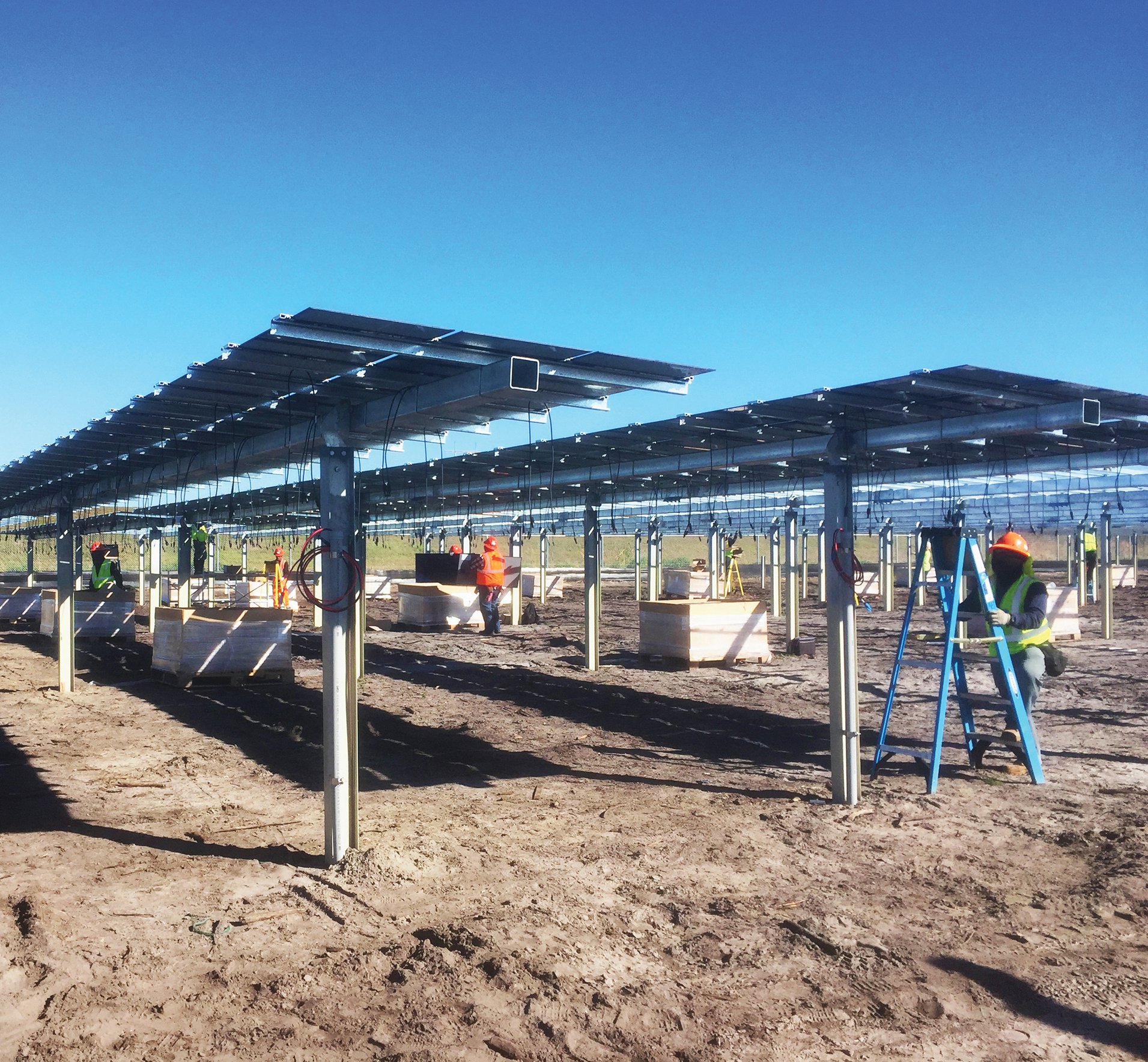
Just how much risk? Consider that a midsized (50-MW) solar farm will likely require as many as 25,000 individual foundation posts. A site with poor soil conditions could require an average embedment depth of 16 feet, which would require more than 75 linear miles of steel. However, if insufficient geotech information is provided, the contractor could assume an average embedment depth of 8 feet, cutting steel cost in half. A seven-figure cost differential between 8-foot and 16-foot embedments is possible and should be identified early in the project to reduce the risk of change orders later on.

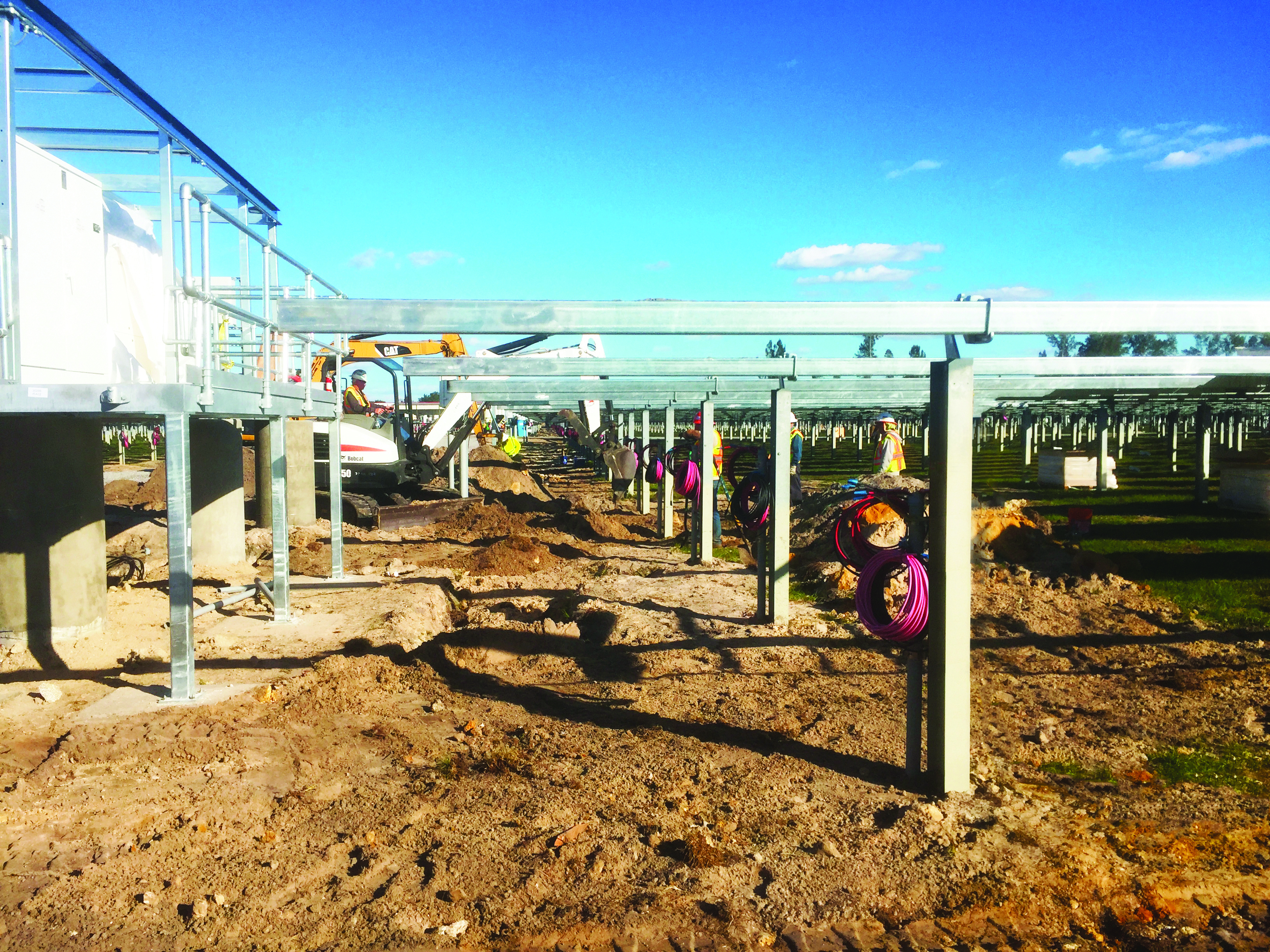
Pile installation — Pile installation costs vary based on the total pile length and embedment length, and whether the piles are driven or pre-drilled. A pile test report should include pile drive times and any abnormal conditions that are experienced during the installations. If pre-drilled piles will be required on the site, that should be noted in the geotech report. This would allow the contractor to develop a more accurate cost estimate and better define the schedule for pile installation and the overall project.

Pile corrosion design — A detailed geotech report should include details on soil corrosivity — information that is critical for steel pile corrosion design — and should include measurements for electrical resistance, pH, sulfates, chlorides and organics. The report should include the interpretations of a qualified corrosion engineer regarding the corrosion severity for concrete and steel, and corrosion rates for galvanized and carbon steel. Recommendations should also be provided for the level of corrosion protection required to achieve the desired design life of the project.

While inverters and other project equipment may have, for example, a 15-year or 20-year design life, they may be upgraded or replaced over the project’s life. Piles, however, cannot be replaced — at least not at a reasonable cost. Therefore, piles should have a corrosion design life that will last the duration of the project’s life span.

Underground cable sizing — Thermal resistivity data from the geotech report is also needed to size underground cable. These values vary based on moisture content, density and other factors. Sandy, damp and coastal soils have lower thermal resistivity, for example, and pull heat away from cables, making it possible to specify smaller cable sizes. Clay soils with higher thermal resistivity — like those typically found in Arizona and Texas — are less apt to allow for dissipation of heat and call for larger cable sizes and trench widths, or the use of imported backfill with lower thermal resistivity.

IMG_2518_croppe

Equipment selection — Equipment selection has a large impact on project success, so it’s important to procure equipment that will operate reliably over the life of the project. Some module manufacturers are making this goal more attainable by offering package solutions that include modules, trackers, inverters and O&M in their scopes of supply. By taking more control over system design and operations, these manufacturers are able to make performance guarantees and bring predictability to owners’ O&M costs.

Even so, due diligence still must be performed on all equipment. That includes working with manufacturers to define specifications and performance requirements. Keep in mind, manufacturers are not required to provide documentation for quality or technical requirements that have not been strictly outlined in contractual requirements.

It’s then necessary to verify performance through testing. Unfortunately, failure rates on solar equipment can be high. In the May 2019 modules scorecard published by PV Evolution Labs, a PV module reliability testing company, 33% of the products tested failed the arc fault test, 21% failed the damp heat test, and 25% failed the humidity freeze test.

Price pressures and industry consolidation remain ongoing concerns, with a steady stream of vendors entering and exiting the inverter market each year. In some cases, utilities have been left with equipment that has neither a warranty nor spare parts supported by a manufacturer.

With new solar projects looming, production at many inverter manufacturers is at full capacity. To meet construction schedules, some utilities find themselves working with smaller, less-established manufacturers — serving as another reminder of the necessity for design verification testing, which should be outlined in engineer-procure-construct (EPC) and vendor contractual requirements.

Safety — Workforce training includes safety, which can present unique challenges on solar projects. Fatigue and repetitive motion injuries are common concerns, given the nature of the tasks performed in installation. When schedules are tight, labor may be required to work through inclement weather or during evenings in poorly lit conditions. Trade stacking — increasing manpower in areas where several construction activities are being performed at once — is also common, especially in areas where mechanical installations are underway. It is preferred to stagger civil, structural, mechanical and electrical activities across the site.

Module installation and wire management — Improper module installation and poor wire management can lead to ground faults and performance issues. That’s why installations should always be completed according to the manufacturer’s requirements, a well defined quality management procedure, and in accordance with applicable codes.

In some cases, it makes sense to ask the manufacturer to send a representative to a project site to confirm proper module installation. This step can deliver added value if the solar installation experiences production problems. If the modules are at fault and they are found to be improperly installed or damaged during installation, the manufacturer’s warranty may be invalidated.

Proper cable tie selection and installation are equally important. UV-rated products are different from UV-stabilized ones. Just because a cable tie is UV-rated does not mean it will enjoy a long life in the field. Industry testing for UV-weathering is not standardized. Soil characteristics, climate and proximity to water should be considered when determining cable tie’s moisture and chemical ratings.

Equipment enclosures — Metal or fiberglass enclosures are typically used to house communication, power and other electrical equipment in the field. It’s important for the contractor to review vendor installation requirements and verify that penetrations are adequately sealed and that the enclosure is correctly mounted and installed. Special sealing precautions are needed to prevent moisture, insects and other pests from entering the enclosure and voiding the manufacturer’s warranty.

SCADA requirements — Often the requirements for operational controls — usually a supervisory control and data acquisition (SCADA) system — remain vague or receive little oversight until the later stages of a solar project. To achieve a useful control system the first time, SCADA specifications should be developed prior to a request for proposal (RFP). That allows the contractor to coordinate with the owner on the development of a detailed architecture that can be validated through factory acceptance tests.

Projects that don’t address SCADA needs early typically have one of two outcomes. The owner may need to update SCADA requirements mid-project, resulting in change orders. Worse, the owner may discover upon the project’s completion that the SCADA system is not compatible with its existing network. In that case, additional work is needed to retrofit, standardize and integrate the SCADA platform with the existing network, resulting in unanticipated and unnecessary costs.

Construction quality — One of the most effective ways to control project quality is to begin by constructing one complete row of a solar installation as a mockup. This mockup sets precedents for the subcontractors as they complete the remainder of the project, particularly for critical elements like module installation and wire management.

A mockup row also provides the owner, engineer and contractor the opportunity to review the installation jointly, provide feedback and align on quality control, cable management, safety, O&M needs and other issues. A mistake caught in a mockup installation can minimize significant challenges down the road.

The mockup installation can also be helpful in the development of a quality plan and inspection checklist. Daily use of this checklist on individual rows can also aid in early error detection.

Labor — A mockup row can also serve as a training tool for the labor force completing the installation. Training is critical because solar installations tend to be located in rural areas, where local labor may or may not be experienced in such construction. It is typical for the contractor to staff the construction leadership and then recruit the majority of workers from the local labor force. Due to budget limitations or labor availability, most are unskilled craftspersons who will require ongoing training throughout the life of the project.

BENEFITS OF AN ENGINEERING-LED EPC SOLAR PROJECT

Most utility-scale solar projects are completed using the EPC contracting approach. Proposals are typically solicited for an installation of a given size, with the project awarded to the EPC contractor with what the owner deems to be the preferred solution. That contractor then takes complete responsibility for project delivery, from design, procurement and construction through commissioning and final handover of the project.

In some cases, EPC teams are led by general contracting firms that take responsibility for procurement and construction, while subcontracting design. Others are led by full-service design and construction firms that perform all project functions in-house.

There are many reasons why the latter, single-source EPC approach is preferred for solar installations. First, design and construction teams are housed under a single roof. Both seek input from the other and are brought in earlier in the process than in general contractor-led EPC relationships. A general contractor that subcontracts engineering services is less likely to pay the engineer to make regular and frequent site visits. With an engineering-led EPC, it is not unusual to have an engineer on-site throughout construction.

Internal coordination of the EPC team also creates a complete link for every phase, from design through construction. Project continuity virtually eliminates scope breaks where disagreements over roles and responsibilities can develop. In an engineering-led EPC team, the same engineers that work on the design can provide support during construction, commissioning and performance testing.

Utilities that are eager to complete solar projects on time to qualify for tax credit programs benefit in particular from experienced, engineering-led EPC teams, which are often able to navigate the challenges outlined in this paper, streamline schedules and deliver both a high-quality project and owner peace of mind.

PROJECT STATS

Client
Example Company

Location
Example location

Completion Date
Date

Lorem ipsum dolor sit amet, consectetur adipiscing elit. Nullam cursus lectus sed vestibulum malesuada. Vestibulum eget eros eleifend, imperdiet nisl et, hendrerit nisi. Sed sed ornare felis. Mauris posuere libero sit amet dui suscipit consequat. Duis elementum libero id pulvinar lacinia. Mauris nunc velit, imperdiet in urna et, pellentesque tempor ligula. Ut neque lorem, aliquam a lorem et, tristique eleifend dui. Curabitur massa quam, volutpat sed imperdiet vitae, elementum vel ligula. Ut purus felis, viverra vestibulum ultricies vel, blandit non nisl. Curabitur fringilla rhoncus nulla vel efficitur. Nulla in est gravida, vehicula sapien quis, consectetur est.

Proin scelerisque scelerisque fermentum. Aliquam fringilla purus arcu, facilisis lacinia neque bibendum eget. Aliquam faucibus tincidunt sapien et scelerisque. Proin tincidunt porttitor ipsum. Fusce vestibulum tincidunt eros, id tincidunt quam condimentum non. Phasellus ac nisi magna. Nullam pulvinar risus quis ligula finibus, nec gravida neque luctus.

Interested in learning more?

SEND US A NOTE