IMPACT OF BIFACIAL MODULES ON PV SYSTEM EQUIPMENT AND OVERALL DESIGN
The use of bifacial modules can impact PV system equipment and design in significant ways. Conventional racking systems for monofacial modules include rails that cross the rear side of these panels. To optimize energy gains in bifacial PV systems, designers need to find ways to avoid or minimize elements that create shade on the rear side of modules. Rails and other structural components can also cover cells, which can lead to hot spots that can damage modules.
To avoid these issues, bifacial PV systems require special mounting systems. Those optimized for bifacial applications typically have narrower mounting rails in their racking and tracker structures. Strategically placed vertical supports are also typically designed to minimize back-ofmodule shading.
Likewise, the junction box on many monofacial modules is located directly behind one or more PV cells. By contrast, most bifacial modules typically are designed to have smaller, low-profile junction boxes located at the perimeter or on the backs of modules.
In a December 2018 white paper, “Bifacial vs. Silicon Modules on Genius Tracker,” GameChange Solar takes a deeper dive in addressing optimal mounting configurations for bifacial modules. The paper argues that mounting modules two-up in a landscape layout helps to minimize degradation. Modules mounted one-up in a portrait configuration, though, produce better financial performance. Actual field results, however, may vary, based on racking and tracker design. In these cases, PV system designer and end users should coordinate with the racking and tracker vendor for bifacial module design, equipment selection and the most effective tracking scheme.
Along with these considerations, multiple other features should be considered in design. Some bifacial modules, for example, are designed with a gap between cells midmodule to minimize cell shading. Modeling efforts should address whether an increase in row spacing is needed or should be suggested.
Height of the tracking system should be optimized, as extra energy production can result when torque tube height is increased.
As power output increases due to the use of bifacial modules, so should cable and overcurrent protection, as well as electrical equipment ratings. Cables and equipment should be sized to handle the maximum currents listed in the PV module data sheets, which may increase some balance of system (BOS) equipment sizes and costs. Higher energy output also has the potential to impact the life of PV inverters. System designers should coordinate with inverter manufacturers to help make sure additional direct current (DC) power generated by bifacial modules will not exceed the ratings of the inverter components or recommended DC/AC ratios. This is a common way of representing this variable in PV design.
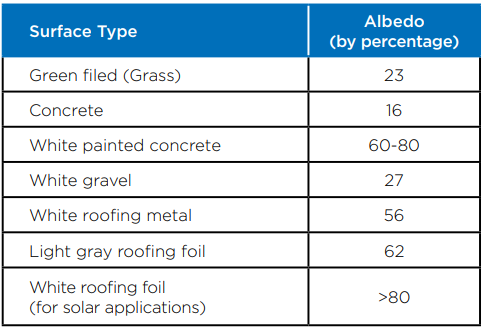
Additional considerations will also need to be accounted for when estimating operation and maintenance costs. For example, it is necessary to factor the cost of cleaning the rear sides of bifacial modules into regular maintenance budgets. Also, vegetation and site management may be more frequent and more involved to maintain higher albedo of the ground around bifacial arrays.

