High levels of alternating current (AC)-induced voltage have been considered a risk for humans and wildlife for years, but few imagined it could pose a threat to nearby pipelines. In recent years, a new threat has been identified — the risk of AC interference corrosion. This risk has caught the attention of both corrosion experts and natural gas providers across the U.S.
Underground pipelines are coated and supplemented by cathodic protection (CP), a technique used to control the corrosion of metal surfaces. Despite the dual layer of protection, it has been observed with increasing frequency that these pipelines can experience AC interference corrosion when collocated with or crossed by HVAC facilities.
Organizations have been compelled to share utility corridors for many reasons, including government permissions for land access, public opposition to infrastructure projects, and the cost of land. While sharing corridors is beneficial in a lot of ways, pipelines collocated with one or more transmission lines for a significant length — at least 1,000 to 1,500 feet — can be exposed to an increased risk for AC-induced corrosion and shock hazards.
There are several ways alternating current can couple with parallel metallic structures:
- Capacitive coupling: The transfer of energy through a dielectric medium such as air between two or more electrical circuits. Capacitive coupling is observed during construction activities when lengths of pipe are resting on wooden skids before being lowered into the trench. The ungrounded pipe segment will behave like a capacitor, which could lead to a hazardous buildup of AC charge. It is common practice to temporarily ground each end of the skidded pipe segments to eliminate the risk for electrical shock. Once a metallic object is grounded, the capacitive effect is no longer a concern.
- Inductive coupling: Caused by the interaction between the electromagnetic field (EMF) generated by HVAC transmission lines and any parallel metallic structure. The current flowing through the transmission line conductors induces a voltage onto the paralleling pipeline by Faraday’s law of induction. The magnitude of interference can be affected by several variables, including:
- Transmission line current
- Cathodic protection current density
- Conductor height, material, phase arrangement and circuit geometry
- Electrical isolation
- Length of parallel collocation
- Pipeline coating quality, diameter and depth
- Separation distance
- Soil resistivity and chemistry
- Substation and pipeline station grounding
- Resistive coupling: Happens when two circuits interact with each other through a conductive path such as soil. During a transmission line fault event, a large amount of current is injected into the earth from the tower ground. Due to ground potential rise caused by the injected current, a pipeline within the voltage gradient experiences a voltage stress because of the low AC potential of the pipe and the high potential of the soil surrounding the coating. This can result in severe coating damage and even direct arcing between the two structures.
Risk Assessment and Mitigation
There are many variables that play into whether and how collocated pipelines experience AC interference corrosion. Proper identification and analysis of these variables is essential when determining the degree of interference and the appropriate mitigation technique.
Environmental Factors
Mapping route geometry and environmental conditions can help identify locations especially susceptible to AC interference. When analyzing the route, it is important to note that the length of collocation and separation distance directly affect the risk for AC interference. That risk increases as the collocation length increases, as well as when the separation becomes narrower. Collocations over 1 mile and pipelines within 100 feet of HVAC transmission lines should be considered high-risk.
Low soil resistivity directly contributes to an increase in AC-induced corrosion rates. Water crossings, swamps and soil with high moisture content will exhibit low resistivity and should be considered high-risk areas. Collecting soil resistivity measurements in future pipeline surveys should be considered.
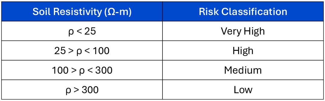
Source: EN 15280, “Evaluation of AC Corrosion Likelihood of Buried PipelinesApplicable to Cathodically Protected Pipelines,” 2013.
Collocation discontinuities also factor into the risk. Locations where the pipeline enters or deviates from the transmission line right-of-way have an increased risk for AC-induced corrosion due to disruptions in the electromagnetic field caused by the changing route orientation.
The transmission line structure can also provide clues as to its likelihood of causing interference. Lines supported by large, steel structures are likely to have higher steady‑state current, whereas small, wooden structures, which commonly support distribution circuits, generally have lower steady-state current. Circuits with one or multiple (bundled) large conductors associated with each phase also tend to have higher steady-state currents. When observing the tower structure, note the size and length of the insulators between the tower and phase conductor. Longer insulators generally translate to higher voltage circuits. One way to roughly estimate transmission line voltage is to multiply the number of insulator disks by 15.
Pipeline Characteristics
Several characteristics of the pipeline can influence the degree of AC interference.
High-quality pipeline coatings are among the main variables that contribute to elevated AC voltages because of the coatings’ inability to self-ground. Most of the induced voltage is retained by the pipeline because of the absence of coating defects. Therefore, old coal tar-coated pipelines typically experience fewer AC interference issues than superior fusion-bonded epoxy-coated lines.
The presence of pipeline insulators can have a beneficial or adverse effect on the degree of AC interference. Electrically isolating segments of pipe can reduce AC voltages (due to a reduction in continuous, parallel pipe length); however, locations where electrical isolation exists can also experience a spike in AC voltage because the induced current is unable to flow past the insulator and attenuate farther down the pipeline, causing a charge buildup.
Factors as simple as diameter and depth of the pipeline can make a difference. As pipeline depth and diameter increase, the magnitude of AC interference is reduced, assuming all other variables remain consistent.
Coupon Test Stations
Test stations used to collect AC voltage measurements can provide valuable insight regarding the degree of interference. In accordance with the standard from NACE International on mitigation of AC and lightning effects on metallic structures (SP0177-2014), a steady-state touch voltage of 15 VAC or more with respect to local ground is considered a shock hazard, and the installation of AC grounding systems is necessary.
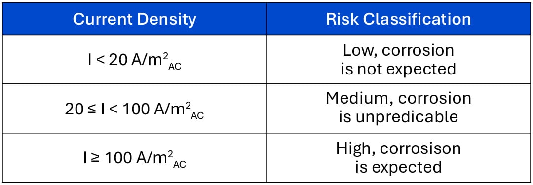
After determining that the pipeline is safe to work around, one can focus on the corrosion risks. When current is induced onto the pipeline and begins to flow longitudinally, it is going to look for a path to return to its source. The path of least resistance is most likely through a pipeline coating defect, and the subsequent discharge results in accelerated corrosion. The probability of AC-induced corrosion can be predicted based on current density levels. NACE International provides the following guidelines:
AC coupons are small, bare pieces of steel used to simulate a pipeline coating defect. The density of the current leaving the coupon surface can be measured and used to gauge the pipeline’s risk for AC corrosion at actual coating defect locations. Readings collected from these coupons can also assist in real-time monitoring of AC density levels, which are always fluctuating based on hourly current demands and seasonal variations in the soil’s electrical resistance. The AC coupon should be installed at pipe depth, within 1 foot of the pipe and facing the pipe. The collection of AC pipe-to-soil and current density measurements (if possible) should be included in all corrosion surveys of pipelines collocated with HVAC transmission lines.
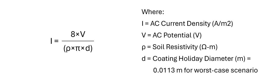
If no coupon test stations have been installed along the pipeline route, the AC current density still can be calculated if AC voltage and soil resistivity data is available:
It should be noted that elevated voltages do not necessarily mean that the pipeline is at risk for induced corrosion, as soil resistivity and coating defect geometry also influence the current density levels. The opposite is also true, as it is possible for AC corrosion to occur at very low voltage levels. Temporary coupons are also effective in determining current density without the use of calculation or soil resistivity data. Coupon probes are commercially available and can be used to easily measure current density levels in the field where permanent coupon test stations are not present.
AC Modeling
Before taking the necessary steps to mitigate corrosion and shock hazards along the pipeline, it is vital to understand the degree of interference and how the installation of grounding will impact voltage and current density levels along the entire pipeline length. The nature of alternating current makes this difficult to determine without the use of computer-based modeling software. Therefore, modeling of the high-voltage corridor is recommended if a preliminary review of the pipeline route (proposed or existing) and/or field measurements indicates the structure may be at risk. AC modeling software can accurately predict the magnitude of interference and help determine the appropriate location and extent of required grounding installation.
AC Mitigation System Design
AC mitigation techniques include designing and installing grounding systems to reduce coating voltage stress during network faults, maintain steady-state AC potentials below the 15 VAC safety threshold, and lower current density to provide protection against AC corrosion. The following methods have been effective in mitigating AC interference:
- Parallel grounding conductors: This is the most commonly utilized AC mitigation technique. The installation of a parallel copper or zinc grounding wire will reduce AC voltage and current density levels experienced by the pipeline and can also be used to shield the pipeline during a fault event. This wire is often buried at pipeline depth and separated anywhere from 1 to 10 feet laterally.
- Pipeline grounding electrodes: This system consists of grounding arrays (multiple ground rods or zinc anodes) or deep ground wells that are connected to pipelines at strategic locations to reduce voltage spikes. Similar to parallel grounding conductors, these installations are effective during steady-state and fault conditions.
- Fault shielding: HVAC transmission lines running parallel to underground pipelines can discharge fault current, causing high coating voltage stress and even direct arcing in soil, which damages pipeline coatings. Fault shielding can be installed between the tower footing (or substation grid) to reduce pipeline voltage stress and intercept a possible arc. It should be noted that the installation of fault shielding cannot be fully relied upon to intercept an arc. While these conductors may help to reduce fault damage, the presence of low-resistance shielding conductors can also promote direct arcing between the grid and the conductor where arcing otherwise would have not occurred if the shielding were not present. Fault shielding should be considered with care.
- Gradient control mats: During steady-state or a fault condition, high levels of AC voltage can be present along the pipeline. Any person near the pipeline can be at risk for shock. Gradient control mats installed around above-grade appurtenances provide protection from hazardous step and touch voltages.
Conclusion
As the demand for natural gas increases, building robust pathways for pipelines will be extremely important. Collocating utility infrastructure can be an attractive option to mitigate challenges from permitting, public opinion and construction costs. However, high-voltage collocations have presented both safety and pipeline integrity risks to natural gas providers. In the past, identifying the potential ill effects transmission lines could have on the pipelines was a challenge itself. With extensive research and newer technology, it has become easier to identify these risks. Bolstered by that awareness, pipelines and parallel structures can be protected from those hazards. Addressing the risks preemptively can dramatically reduce maintenance and replacement costs and is essential for protecting the public, pipeline personnel and property.